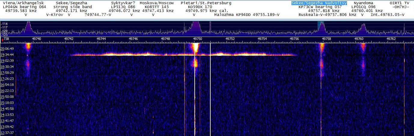
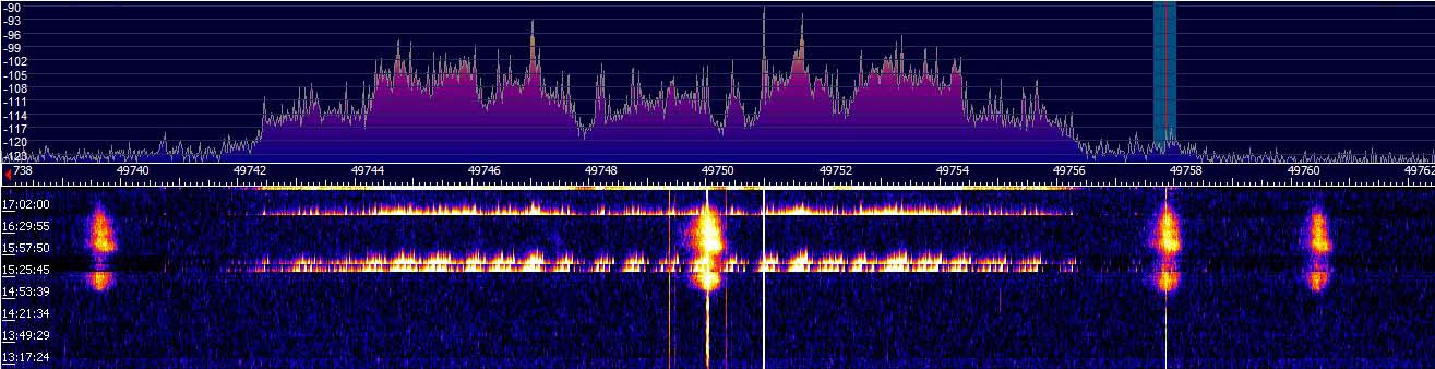
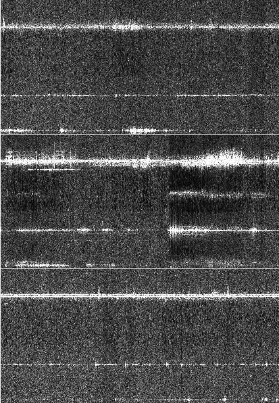
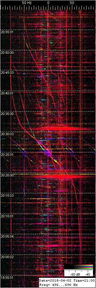
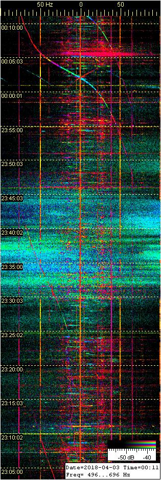
Uudenvuodenpäivän iltapäiväinen revontulipurkaus oli varsin voimakas, ja sekaan leimahteli leveitä voimakkaita yläsalamapurkausten radiokaikuja. Tavallisesti aurorapurkausta ja tällaisia voimakkaista leveitä yläsalamaheijastuksia ei näy yhtaikaa, vaan leveät sähkönpurkausheijastukset esiintyvät ennen revontulipurkausta, tai sen jälkeen.
Arvaan purkausten yhtaikaisuuden ja voimakkuuden saattavan merkitä, että aurinkotuulen puhuri on tuonut aimo annoksen taivassähköä. Nyt aurinkotuulen tuomaa sähkövarausta lienee tullut riittävästi purkautumaan samanaikaisesti sekä revontulina, että yläsalamoina…?
Leveät korkean taivaan sähkönpurkausheijastukset näyttävät liittyvän joskus revontulten alkamiseen tai päättymiseen. Niin kävi nytkin. Aurorapurkaus taukosi klo 16.45, minkä jälkeen leimahti revontulitutkan nauhalle yksi voimakas leveä sähkönpurkauskaiku lisää. Revontulikaiut näkyvät tällä leveällä nauhalla pystysuuntaisina ‘lieskoina’. Leveät sähkönpurkausheijastukset puolestaan näkyvät vaakasuuntaisina, yläreunaltaan sahalaitaisina juovina.
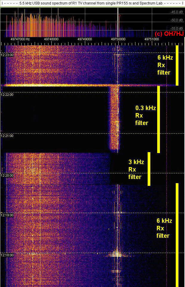
Tutkanauhan alemman ikkunan radiospektrinauhan liikesuunta on ylhäältä alaspäin. Aikaleimat nauhan vasemmassa reunassa ovat Suomen aikaa. Päiväys on kuvien tiedostonimessä. Taajuudet näkyvät kilohertseinä taajuusasteikolla spektri-ikkunoiden välissä.
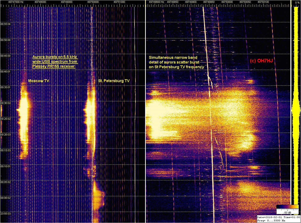
A simple multi-frequency reception experiment on part of 49750 kHz OIRT1 TV channel spectrum with traditional analog HF communications receiver Plessey PR155 which has filter for 6 kHz wide USB. This is a moderate increase of rx bandwidth which allows receiving two instead of previous one TV tx carrier frequencies at the same time with single aerial and receiver. Here the two freqs are Moscow TV and St Petersburg TV carriers about 3 kHz apart from each other.
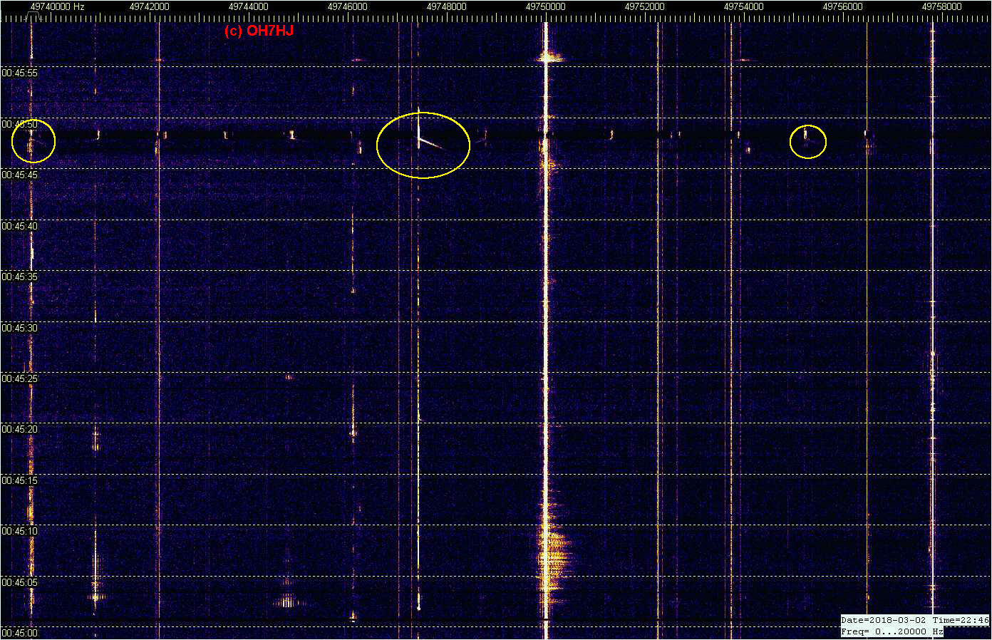
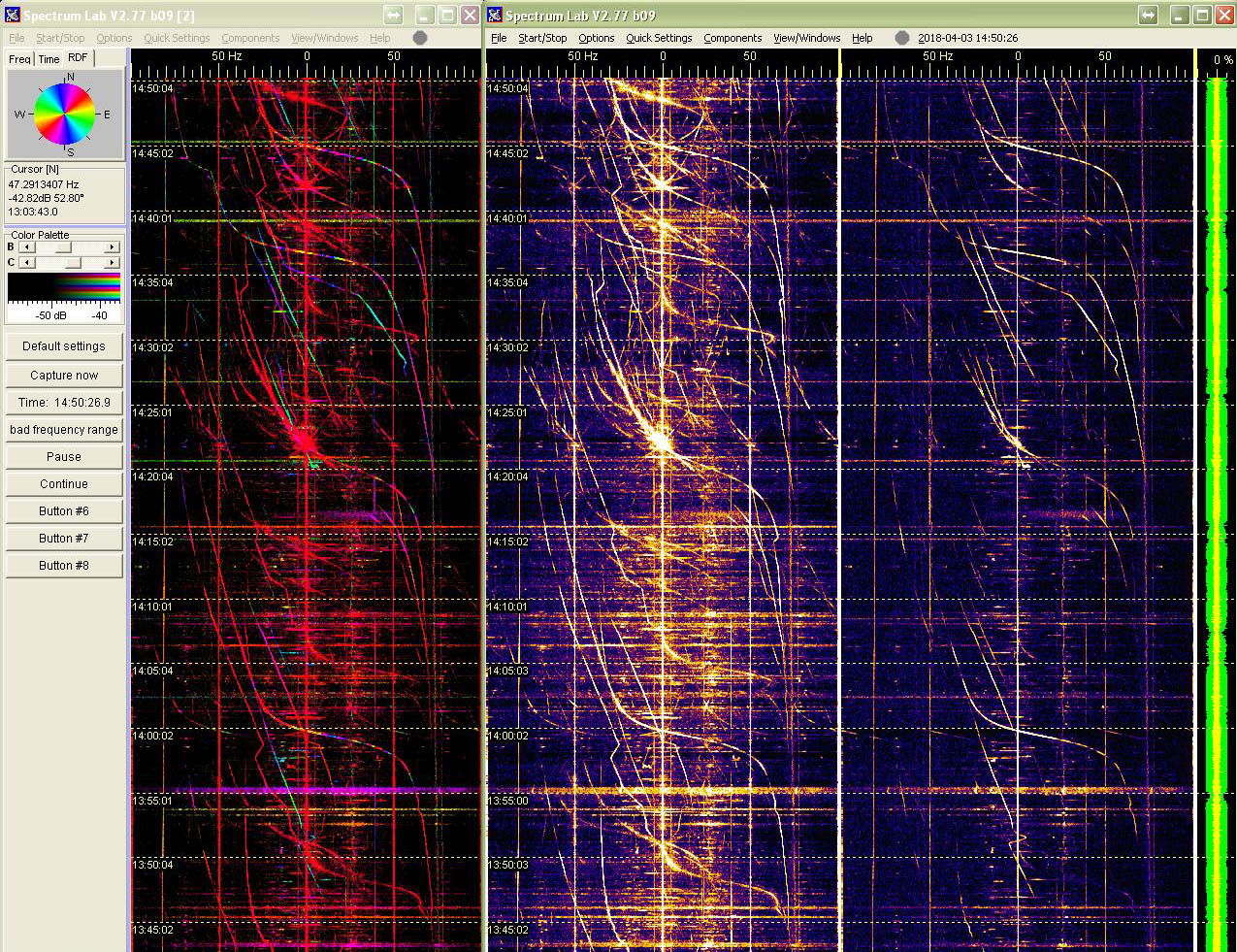
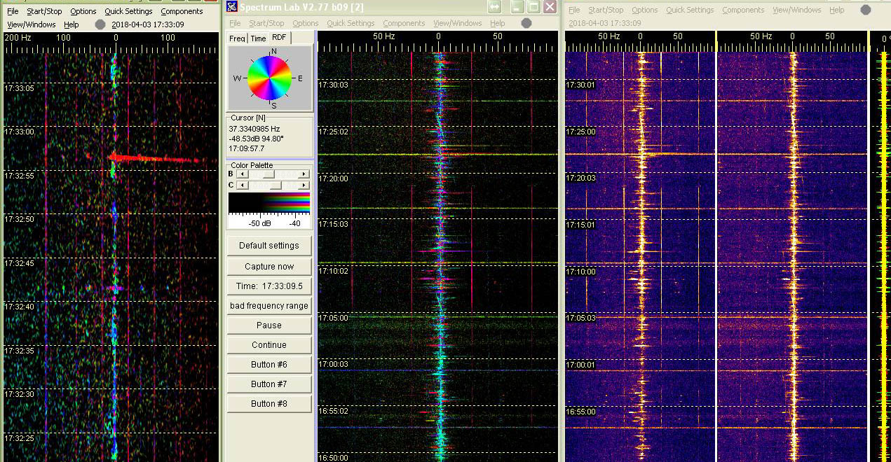
First screenshot shows an aurora discharge burst at left on 5.5 kHz wide bandwidth Spectrum Lab display from part of the R1 TV channel spectrum. Moscow TV and St Petersburg at wide spectrum strip left and St Petersburg zoomed as detail at right SL strip. Both were received simultaneously with same receiver and aerial. Scale at top of each strip shows frequency as Hz.
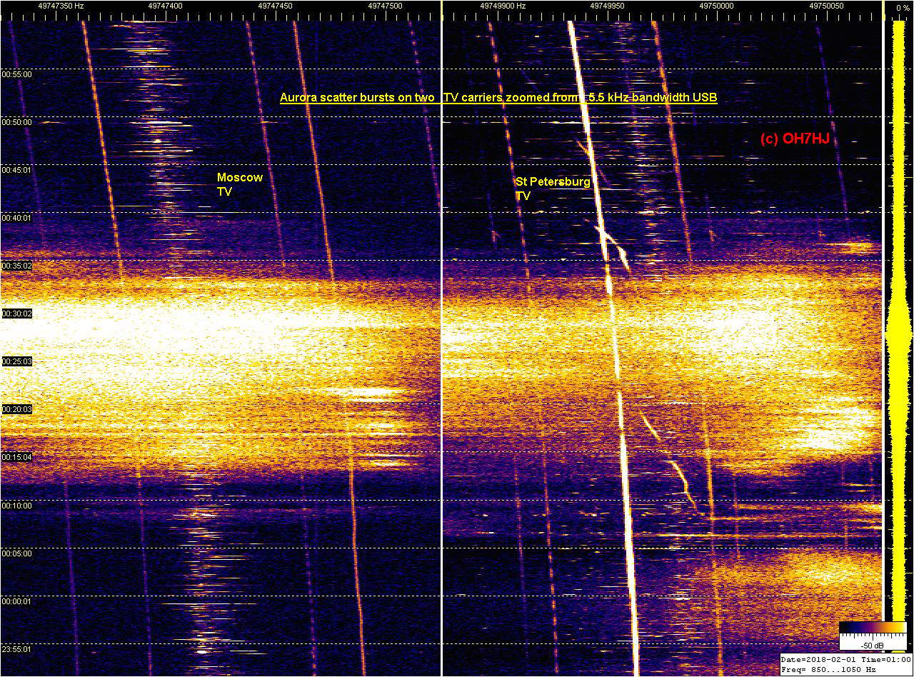
Second screenshots shows at left strip Moscow TV and at right strip St Petersburg TV carrier aurora bursts zoomed still wider with simultaneously plotting another example of Spectrum Lab reading the same PR155 receiver through tiny USB audio stick. Sorry for heavy freq drift of the veteran rx and its converter. Neither are near modern stability standards.
The two Spectrum Labs reading receiver sound through an USB audio dongle consume minimal amount of computer power. The same computer reads and plots at the same time sound inputs from two more 50 MHz ham receivers with still one SL example, plus listens to aircraft ADS-B signals with a RTL1090 SDR to plot them on Planeplotter map: maanpuolustus.net/pages/tutka/
This makes a single computer monitor, analyze and save simultaneously 6 spectrum strips and 5 frequencies. Processing power of this pre-Millennium era Fujitsu Scenic desktop running multi analog rx’s and SL windows is about similar to modern Raspberry Pi. Multi frequency and multi spectrum analysis from wide band audio sound feed from single receiver and aerial appears feasible.
On third screenshot an example of how switching Plessey receiver filters affect monitored bandwidth visible on Spectrum Lab strips.
Filter responses are rather bumpy which is normal for analog receivers like PR155. Modern SDR’s produce nice flat and straight frequency spectrums from their digital filters. I hope that I can get some of the new wide audio SDR’s work in my computers to continue multi frequency experiments with.
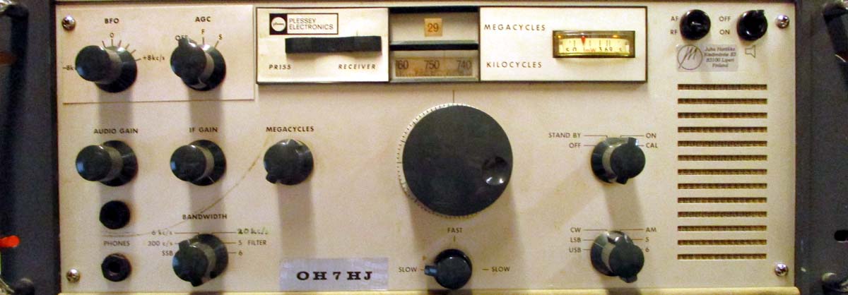
Equipment pics: A 50 MHz converter equipped Plessey PR155 HF receiver dating from early 1970’s was used with this experiment because it was my only rx that could listen to rather wide audio USB with its AM filter of about 6 kHz bandwidth and adjustable beat.
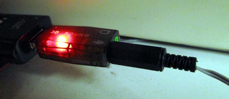
Only digitizing device between the PR155 receiver and computer was an inexpensive USB sound stick.
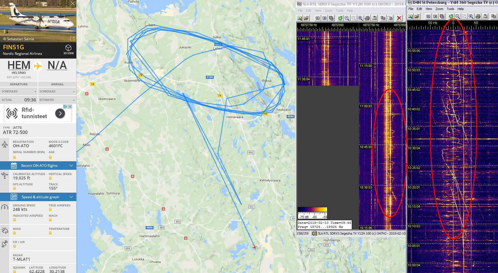
A regular repeating flight pattern doppler appeared on St Petersburg TV and Segezha Nadvoitsy TV strips. It appeared to belong to an ATR plane of flight FIN51G circling around. Doppler vanished as the plane apparently descended below Tx radar horizon for landing to EFJO.
FR24 map view plotted some irregularities to its track. Reason is that this ATR carries only the ‘old style’ mode A/C transponder which does not transmit GPS location of the aircraft.
The FR24 receiver network uses for non-ADS-B mode-S transponder flights MLAT means of locating by its signal time difference of arrival (TDOA). MLAT is less accurate than ADS-B and causes deviations of plane location here visible as aircraft fake sudden jumps southeast on the FR24 playback map. Dopplers tell its real movements.
Online archive spectrum strips of the circling flight doppler:
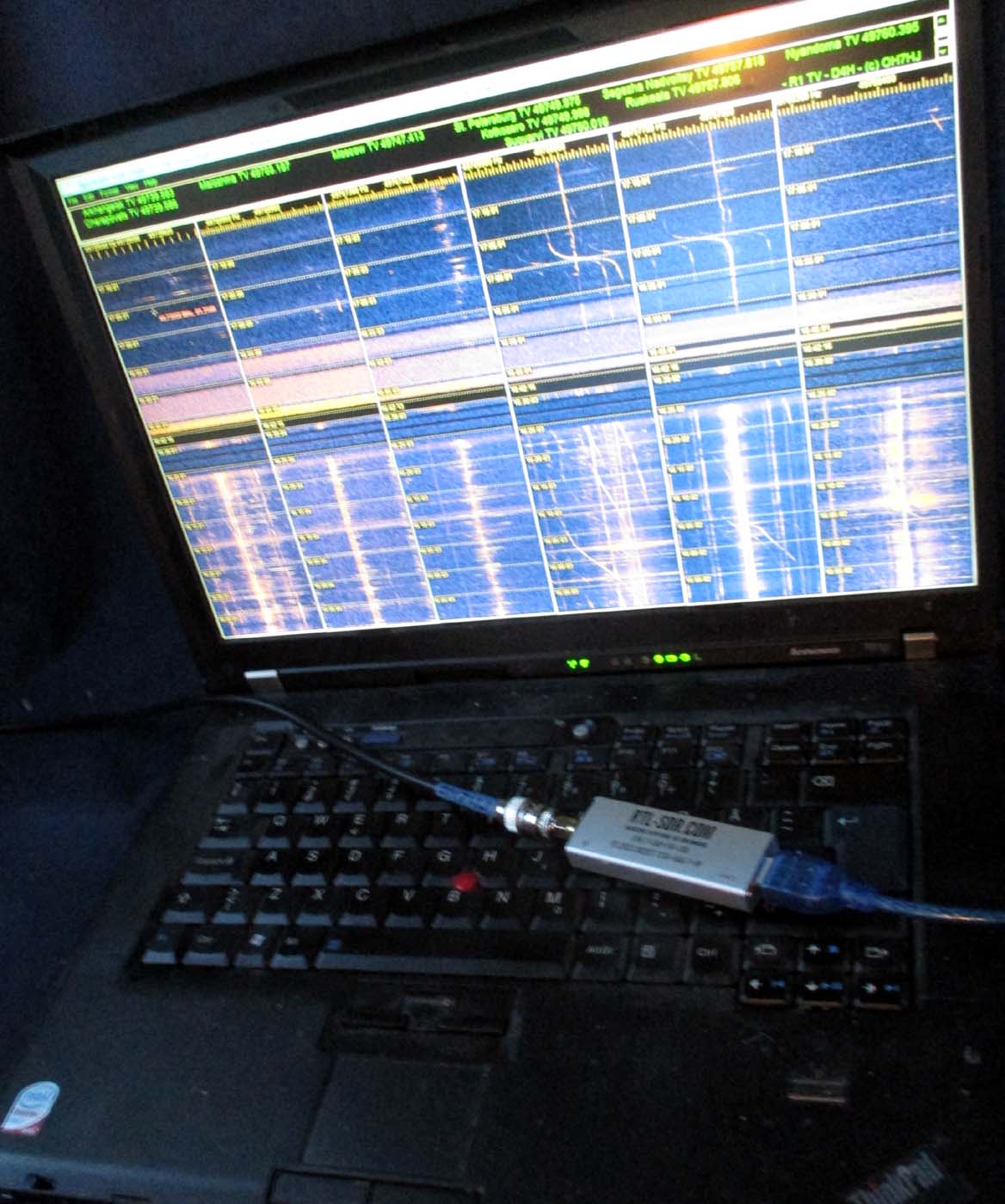
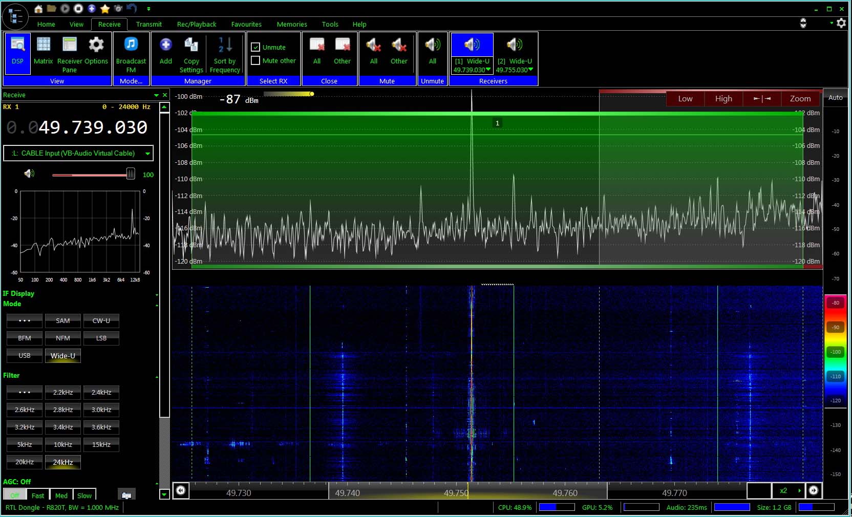
An experiment with a multi frequency receiving configuration aboard a car to see what kind dopplers one gets while moving on road. Receiver was a common RTL-SDR with newest version of software SDR Console V3 which Jesse OH2BIX kindly instructed me how to configure to provide R1 TV wide band voice containing all TV transmitter carriers of doppler interest, thank you!
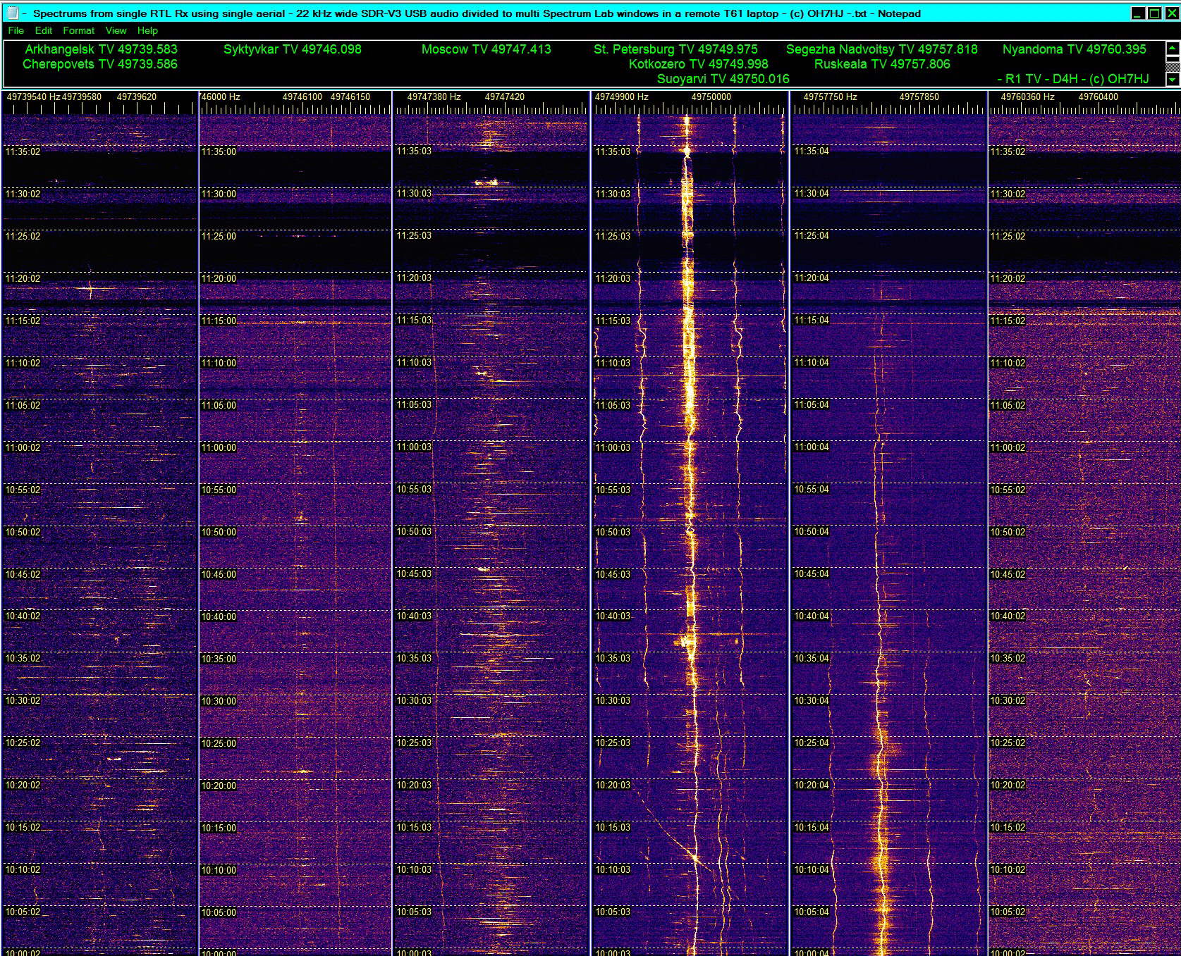
The wide band ‘radar sound’ from SDR-V3 was further streamed through VB-Cable mixer software to 10 separately configured Spectrum Lab windows. From this ‘doppler radar voice’ were separated and plotted narrow band detail strips of eight R1 TV channel transmitters plus a wide band spectrum of entire 22 kHz wide central R1 TV spectrum. This configuration allows monitoring, measuring and saving simultaneously all carriers of the OIRT1 band with a single receiver and single aerial using easily available free software.
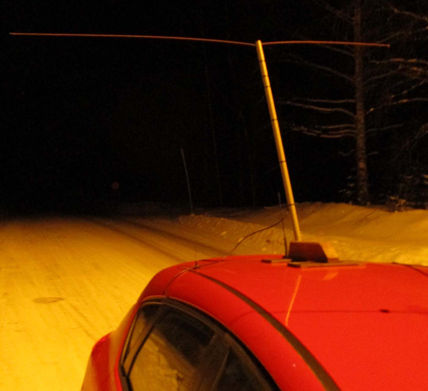
Receiving aerial was a horizontal omnidirectional V-dipole built of carbon fiber rods and of glass fiber broom shaft attached to wooden mounting piece held on car roof by magnets. A Thinkpad T61 laptop was running the receiving software with RTL receiver attached to its USB port.
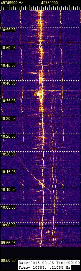
A combined Spectrum Lab display of multi freq receiving experiment detail strips of TV carriers from receiver in a moving car. Some of the carrier freq drift visible on St Petersburg and Segezha TV strips is from RTL receiver drift but much of it is caused by moving car velocity doppler shift. Joutseno TV and FM broadcast mast strong RF field appeared to deafen the RTL receiver stick at around 11.20 to 11.30 oc on this six TV frequencies set of spectrum detail strips causing black sections on them.
The first part of mobile measuring drive was to general direction of south and southwest. As the mobile receiver was driving farther away from Segezha Nadvoitsy TV Tx its signal faded and tended to shift a little down by doppler effect of car velocity. At the same time the mobile Rx was approaching nearer St. Petersburg TV Tx in south which caused its signal level to increase and shift a little upwards by doppler effect. However, when the ‘twists’ of both carriers are to the same direction it is probably caused by RTL Rx freq drift. Those twists that are to opposite directions between the two TV carriers are caused by car velocity doppler shift of reception.
The SDR V3 receiving software was set to stream a 22 kHz wide voice of two wide filter USB VFO’s divided to both stereo channels of a single audio stream channel. This stereo ‘radar voice’ was streamed through VB-Cable to ten independently analyzing and doppler separating Spectrum Lab windows. TV transmitters and their carrier frequencies are on the list above detail strips and there is a freq scale in Hz above each detail strip. Bandwidths of TV carrier detail strips vary between 100 … 200 Hz. Time stamps are Finnish local.
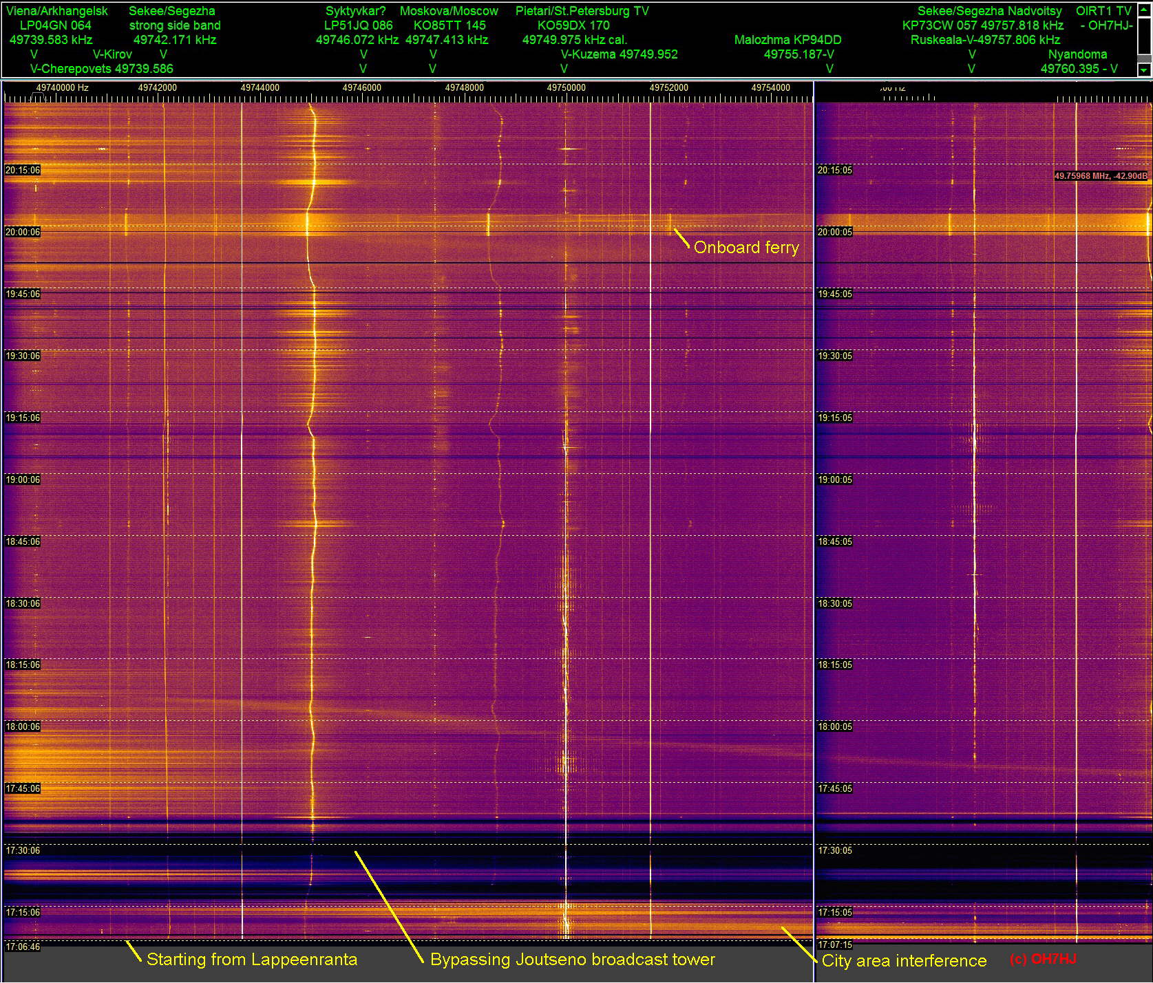
A wide spectrum R1 TV channel slow strip from returning by a route a little different to arrival. In the beginning unstable urban city noise governs the radio spectrum background. Then there are again the already familiar black sections of deafened receiver at the same places as during arrival trip. Probable reason for one of the receiver blackouts is the BC-FM broadcast tower strong RF field.
Background interferences gradually settle down when driving through less populated environment, with an exception of the car onboard a ferry. The open lakeside together with steel deck of the ferry appears raise background noise and interference levels.
Aircraft scatter dopplers are visible as slant lines on the St. Petersburg TV carrier at about 17:12, 18:08, 18:12, 18:23 and 19:08. Parallel to carrier sets of vertical lines are TV 50 Hz side bands. Short sideways spreading marks on many TV carriers are natural scatters like EDS of high sky lightnings. Continuous wandering unstable interferences are coming possibly from car electronics. Time stamps are Finnish local.
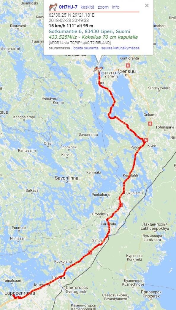
The spectrum strip attached is combined from two separately analyzing Spectrum Lab windows. First window at left plots the lower R1 TV channel spectrum through left audio channel and the right SL window plots upper spectrum from right audio channel. Return track on map was created online from an APRSdroid software installed to a GPS equipped android mobile phone.
Examples of meteor scatter ‘head echo’ dopplers captured by Esko OH2AUP from live ‘radar voice’ of OH7HJ R1 TV channel online streaming receiver. The receiving setup of this experiment is a 4-element almost omnidirectional 50 MHz horizontal dipole array with an RTL receiver and SDR Console V3 software streaming a 22 kHz wide TV channel spectrum as two wide band USB sound streams divided to both stereo channels of single MP3 online voice audio channel.
The fast sweep multi TV carrier spectrums by Esko show meteor scatter (MS) narrow dopplers scattered from the very fast velocity of meteors striking down to upper atmosphere and creating ionized trail which scatters TV carriers of 6m band R1 TV channel. Some of the MS doppler pics show meteor dopplers simultaneously on two TV carrier frequencies.
These actual MS head echo dopplers are rather weak which makes it difficult to capture them on low power radio beacons. With high power beacons like these TV carriers meteor dopplers are much easier to spot. Their usual spread spectrum ‘tails’ following meteor head echo dopplers are strong and long lasting which makes the electric discharge tail scatters very easy to capture compared to head echo dopplers of actual meteors.
However, these natural ionospheric electrostatic discharges alone are not necessarily evidence of actual meteor hits. Also, not all meteor head echo dopplers trigger these spread spectrum electric discharge tails. Natural high sky electric discharge scatters (EDS) occur all the time and vast majority of them appear lack any evidence of meteor head echo dopplers. This suggests that most of these longer than MS head echo doppler lasting natural ionospheric discharges are ignited spontaneously, possibly by voltage of naturally accumulating atmospheric electrostatic charge exceeding threshold level of ionospheric electricity discharge.
Meteor Scatter Spectrum Strips
Esko tells that the attached pics are copied with a single audio channel spectrum software so the lower and upper R1 channel TV carrirers show on the same MS strips. Fortunately they overlap so they can be spotted.
These strips do not have frequency or time scales but his fast registered strips have a sweep of 43.066 Hz per pixel and zero beat is the low edge os the strips representing freqs 49739 and 49755 kHz. Middle registered strips are 4 times slower.
For example, the highest strong carrier of this middle registered MS strip is St Petersburg TV and below the center one with many EDS is Moscow TV. Near low edge is Syktyvkar TV: midle20180227060100_20180227060739 - 7000 - 12000 Hz - MS doppler up left - MS head echo dopplers from online live OH7HJ radar stream captured by OH2AUP.gif
Online Radar Voice
The online multi-static radar voice is freely available for online listeners of AS dopplers as well Es and Aurora scatter or MS spotters. Lower R1 band is on left stereo cahnnel and its audio zero beat is 49739 kHz. Higher TV band starts at 49755 kHz zero beat and it is on right stereo channel.
The sound can be picked up from standard web browser through a virtual audio cable software like VB-Audio Cable by setting it as ‘Default Audio Device’ on windows playback devices menu. Then the virtual cable is selected as input audio device for the sound spectrum analyzer software you prefer. Set it listen to left stereo channel for low R1 TV band carriers and to right stereo channel for high band carriers.
These streams are rather easy to spot by anyone familiar with audio spectrum analyzer software like Spectrum Lab. Please ask me for ready Spectrum Lab INI or USR setup files for either wide band R1 carriers or for detail strips of each TV carrier.
More of Esko’s MS head echo dopplers captured from the live audio radar stream are attached below.
For listeners of the online ‘radar voice’ of R1 TV channel carriers here are appx. audio frequencies for some easily visible TV transmitters from the stereo audio stream to help with configuring spectrum analyzer software for remote monitoring with one’s home computer:
Please notice that there is some time delay with the online internet audio transfer. I am not skilled enough with sound streaming software to make it transfer time codes. Advice with exact streaming software is appreciated!
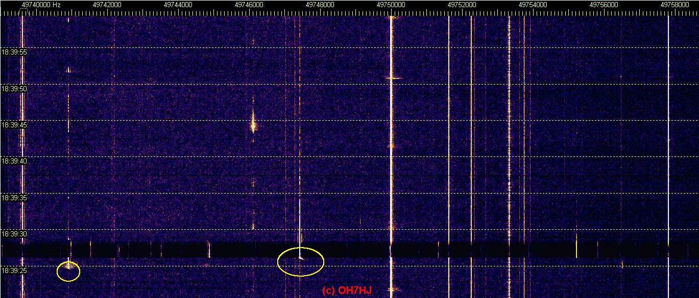
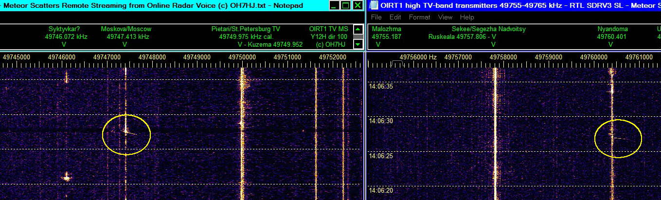
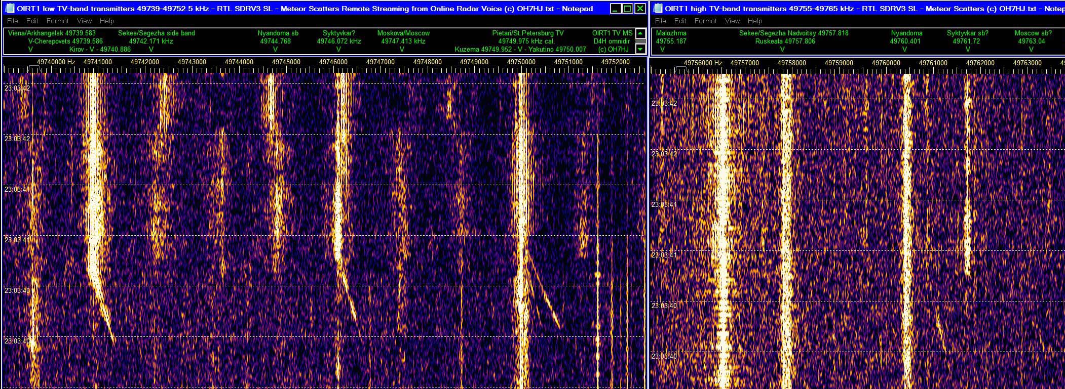
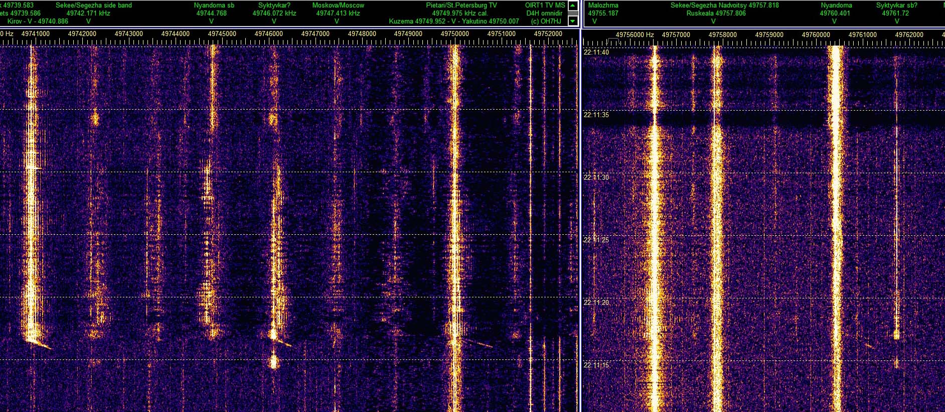
First pic shows a downwards in frequency shooting momentary doppler is distinctive mark of a meteor scatter (MS) head echo doppler. Usually but not always the MS head echo dopplers are immediately followed by a ‘tail’ with only little or no doppler shift. Instead of shift, these ‘tails’ have a spread spectrum.
The spectrum spread is a characteristic mark of radio waves scattered from air ions accelerated by electrostatic discharge. One may suppose that high atmosphere spread spectrum scatters are created by atmosheric electricity. Usual causes of these electric discharge scatters (EDS) appear to be high sky lightning discharges.
On second pic appear to be two MS head echo dopplers after each other on Kirov TV freq triggering immediate EDS’s scattering sets of 50 Hz side bands that almost hide the actual meteor head echo dopplers in the begin. It is usual that the MS head echo doppler radio scatters are very weak but the apparent high sky electric discharges they usually trigger produce a lot stronger radio scatters showing as kind of meteor scatter ‘tails’.
Third pic shows two MS head echo dopplers on Kirov and Moscow TV carrier freqs with immediate EDS tails showing sets of 50 Hz TV side bands.
Please click pics to open them. Receiving aerial for these pics is a 6-over-6 horizontal 6m band yagi pointing east. Receiver is an inexpensive RTL dongle used with SDR-V3 and Spectrum Lab softwares. Time labels on strips are UTC + 2 h Finnish local. Frequency scales are on the top of strips as Hz.
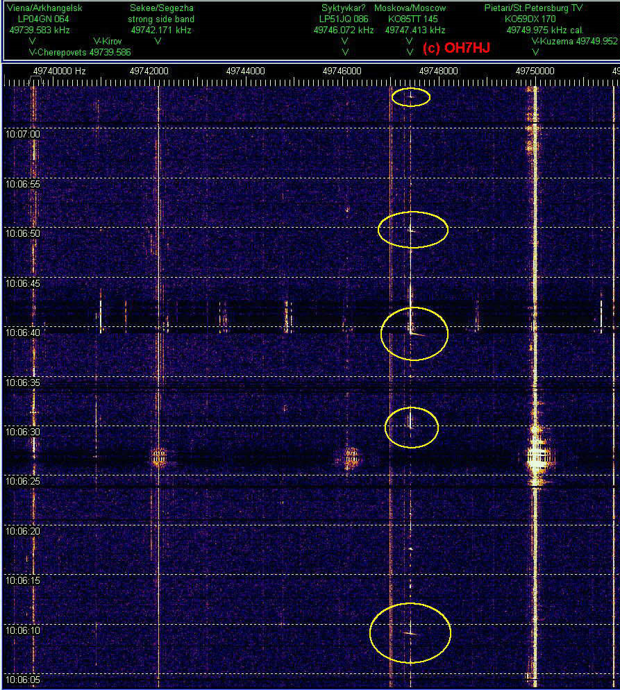
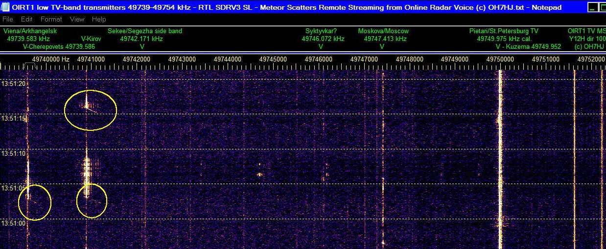
Some meteor scatter head echo dopplers have no ‘tail’. This may be because there happens not to be any high voltage atmospheric electricity to discharge at the point of these meteor high sky strikes. First pic shows MS head echo dopplers without EDS tails.
Most electric discharge scatters (EDS) visible on specrum strils appear to occur without any marks of meteor doppler initiating them. This suggests that either the MS head echo dopplers are too weak to register on receiver strips or the high sky electric discharges are initated spontaneously without help from meteor strikes.
Spectrum strip on second pic has registered three MS head echo dopplers. The longest them is on Moscow TV frequency. Another is on Segezha Nadvoitsy TV. Then there is a weaker one on Moscow TV. These MS hits have very short and weak EDS tails only.
The third screenshot has captured 5 meteor scatter head echo dopplers on Moscow TC frequency. The center one of the dopplers shows stronger than the others. It appears to have initated an EDS ‘tail’ that is strong enough to scatter TV carriers and side bands on wide bandwidth and apparently on many TV transmitters.
Automatic Spectrum Lab periodic screenhots. Two meteor scatter head echo dopplers on Moscow and Kirov TV freqs are initiating immediate ‘tails’ of TV carrier electric discharge scatters and TV 50 Hz side band sets.
From the second pic a sharp observer can find two sets of faint meteor scatter head echo dopplers scattering sets of TV 50 Hz side bands. The following ED scatters are so strong that they almost hide the triggering meteor scatter head echo dopplers.
Third image show a faint meteor scatter head echo doppler initiating EDS on Kirov TV freq and soon after it a stronger MS head echo doppler on Moscow TV freq producing strong and wide enough EDS tail to momentarily raise receiver AGC and put the strip background black.
I started yesterday observing MS head echoes on R1 TV carriers with setup that experienced MS spotter Esko OH2AUP kindly instructed. With new SDR-V3 wide band multi freq setup I could monitor most of the TV carriers simultaneously to observe MS on them. The aerial is a 2 x 6 -el yagi array for 50 MHz. Receiver is an inexpensive RTL dongle. It seems that I am getting most of the MS head echo dopplers from rather distant TV tx carriers like Moscow, Kirov and Syktyvkar TV. Moscow TV together plot MS head echo dopplers about every 2 … 4 minutes. Closer to me St Petersburg and Segezha Nadvoitsy TV tx’s plot only occasionally, just a few MS head echo dopplers a day. Non-doppler spread spectrum ED scatters are so numerous that they were not counted.
The long baseline meteor doppler observation makes sense when thinking that meteor hits occur very high. It is easier for low horizon aimed TV tx aerial lobes to hit high sky objects from long distance than from close where they are high above the directional patterns of their aerials. Also there is more space to collect greater number of meteor hits between on long rx-tx baseline than between close rx and tx.
Further, high ERP radiated power of TV tx of course brings the usually weak MS head echo dopplers visible easier than on low power beacons. The St Petersburg and Moscow R1 ch TV tx’s have very high ERP power. This should make it practical to copy MS head echo dopplers on their carriers in Central Europe, too. Yagis may be needed for receiving real MS head echo dopplers, however. Meteor EDS tails are much stronger so they are of course visible even with low power receiving aerials.
Remote Listening to MS head Echoes
For those who have no access to 6m band MS receiving aerials I am streaming ‘radar voice’ online as ordinary stereo sound. Spectrum Lab is able to copy remote MS head echo dopplers from this stream through one’s internet browser and virtual audio cable.
I will provide ready Spectrum Lab USR configuration files for MS capturing for those who wish to try. ‘Radar voice’ as online steamed stereo sound: maanpuolustus.net/pages/tutka/
In the future, I have in mind to develope an automatic high sky scatters like MS, Es and ionospheric lightnings locating network of voluntary ham and radio hobbyist receiving home stations. For this, voluntary software developers are needed first. Please let me know if you have coding skills and are interested in joining the effort.
Pics of Strong Meteor Dopplers
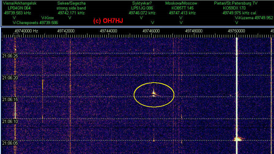
On first pic is a MS head echo doppler strong enough to plot dopplers on three freqs. The strongest is on Moscow TV carrier and the two others symmetrically up and down are possible meteor doppler twins on Moscow TV side bands because they are of same shape as the center one.
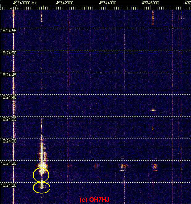
Next pic features a rather long MS head echo doppler on Moscow TV carrier.
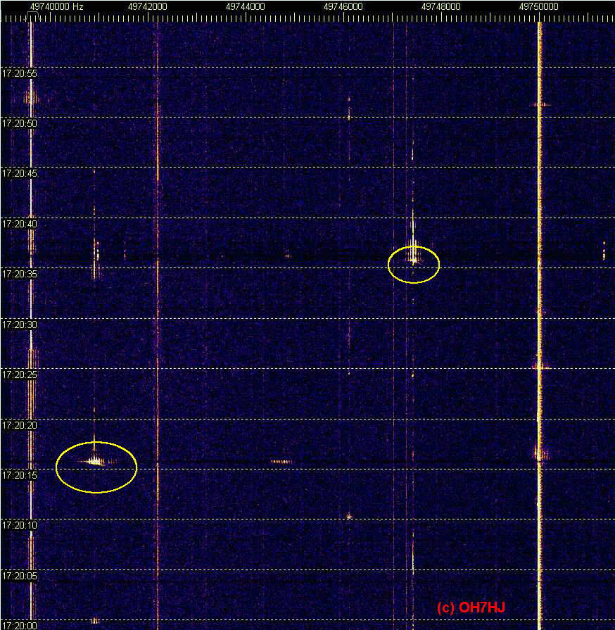
Third image illustrates a long and strong meteor head echo doppler that shows up above at least three TV carrier frequencies: Arkhangelsk/Cherepovets, Kirov and Syktyvkar TV. There appears to be faint fourth doppler above 49748 kHz. These are similarly curved but on different angles so it might be possible to locate this meteor hit by these dopplers.
A couple detail images of meteor scatter (MS) dopplers captured from the online ‘radar voice’. The sound streaming R1 TV channer multistatic radar RTL receiver is now connected to an east pointing 2 x 6 el yagi array. This aerial appears to capture meteor scatter ‘head echo’ dopplers rather well likely because it listens to a large area surrounded by many 6m TV analog transmitters serving as powerful MS beacons.
Small MS dopplers appear every few minutes and fairly long head echo dopplers about a couple times an hour. I have not bothered to count those numerous high sky electric discharge scatters (EDS) occurring every few seconds although some of them are triggered by meteors.
The stereo radar voice contains low R1 band TV carriers starting from 49739 kHz up on left stereo channel and high band R1 TV carriers starting from 49755 kHz up on right stereo channel: maanpuolustus.net/pages/tutka/
Attached images are cropped screenshots from Spectrum Lab (SL) windows registering MS head echo dopplers from online streaming passive multistatic radar stereo voice. These SL windows are set for 1 pixel/FFT bin and 70 mS/line sweep for about one minute meteor scatter strips.
‘Electric Discharge Scatters’ are very usual radio scatters from natural high sky electrostatic discharges like sprites, elves, thunderstorm Es, aurora etc. High altitude discharges ionized air making it conductive enough to scatter radio waves until they rather soon after discharge ceases, cool down and vanish from our receiver strips. So they work quite like little bits of ionosphere except that they have short life time. Sometimes EDS bursts are triggered by atmosphere hitting meteors and are visible on their radio scatter spectrums as their ‘tails’.
High sky discharges appear to be part of global atmospheric electric discharge circuit from high voltage charged solar wind all the way down to ground below our feet. Common ground striking lightnings seem to be the lowest part of the chain of these atmospheric discharges.
Like the thunderstorms, the global daily rate of these natural high atmosphere discharges appears to be constant. This means they occur all the time, although their densest discharge areas appear to move apparently by daily changes of ionosphere.
Spread Radio Scatter Spectrum
A distinctive mark of EDS is its spread spectrum of noise that it modulates to radio waves scattering through it. The higher the atmospheric electrostatic discharges occur, the wider they seem to modulate radio wave scatter spectrums and the longer their lifetime is.
Highest easily visible sources of spread spectrum radio scatters are the Northern Lights with their very strong and wide ‘aurora scatter’ spread noise spectrum, familiar to us radio hams as the ‘aurora tone’.
Unlike fast meteor scatter head echo dopplers, the ED scatters usually have little or no doppler shift which means that they are mostly stationary. Sometimes they have small doppler shift which appears to be caused by high altitude winds blowing them. Instead of the sharp doppler of MS head echoes the EDS have their characteristic spread noise spectrum.
MS Triggered ED Scatters
Usually but not always a strong ED radio scatter follows after a MS head echo doppler. This suggests that the downshooting meteor ionized tail initiates along itself an electrostatic discharge between high voltage charged ionospheric layers.
This electric discharge through meteor trail makes a lot stronger and longer lasting radio scatter than the original meteor trail. Their difference is that while meteor doppler has a wide linear doppler shift of high velocity, the EDS tail has little or no doppler shift but instead a spread noise spectrum.
Because the ED scatters usually immediately follow meteor scatters they are commonly but incorrectly believed to be meteor scatters. In reality, they seem to be scatters from natural high altitude electric discharges triggered by meteor downstrike ionized tails.
Spontaneous Atmospheric Electricity Discharges
However, majority of ED scatters show no MS head echo so they appear to discharge spontaneously, possibly by solar wind charging voltage exceeding breakthrough limit to lower layer of ionosphere.
The high atmosphere discharges strike step by step down to the lower layers of ionosphere until the accumulated atmospheric charge finally finds its way down to ground, usually by a charge carrying high vertical wind rotation of a thunderstorm cloud. When a thunderbolt strikes ground the atmospheric electricity circuit is closed.
Natural ED scatters are quite like any ionospheric propagation better visible on lower radio frequencies. That is why there are a lot of them on low VHF bands like the 6m band. They can be heard also on HF when the high background interference allows.
As part of the global atmospheric electricity circuit the high sky ED’s create very many effects observable with radio waves. Old hams were correct when calling the background noise audible through their aerials and receivers as ‘static’, meaning natural electrostatic atmospheric noise (QRN).
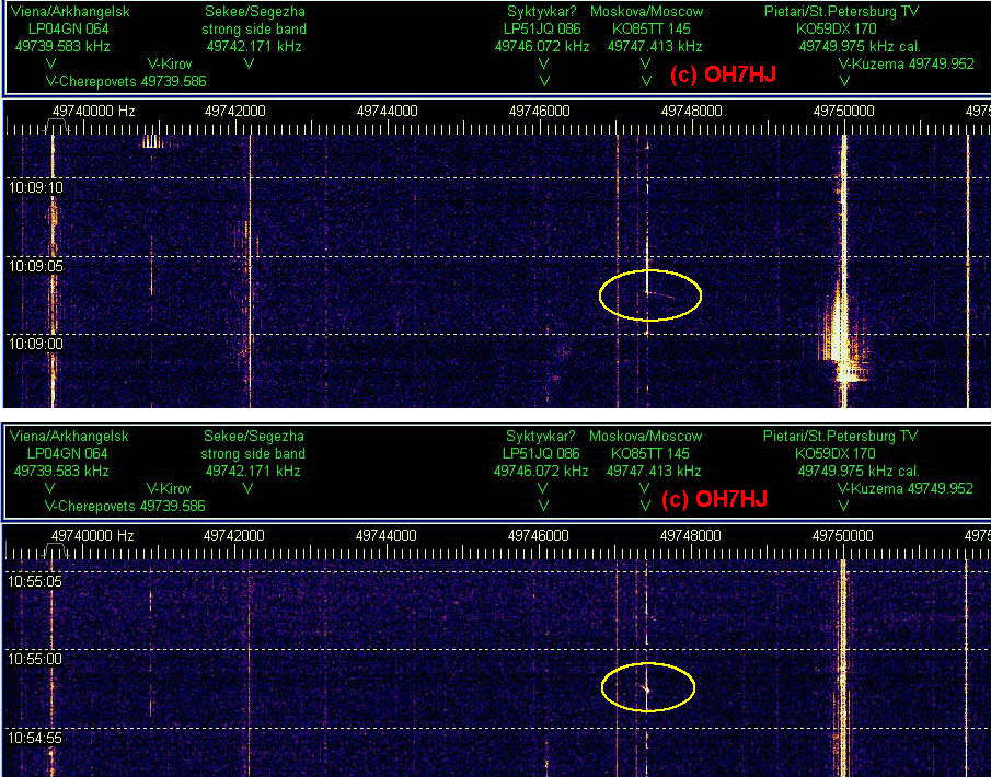
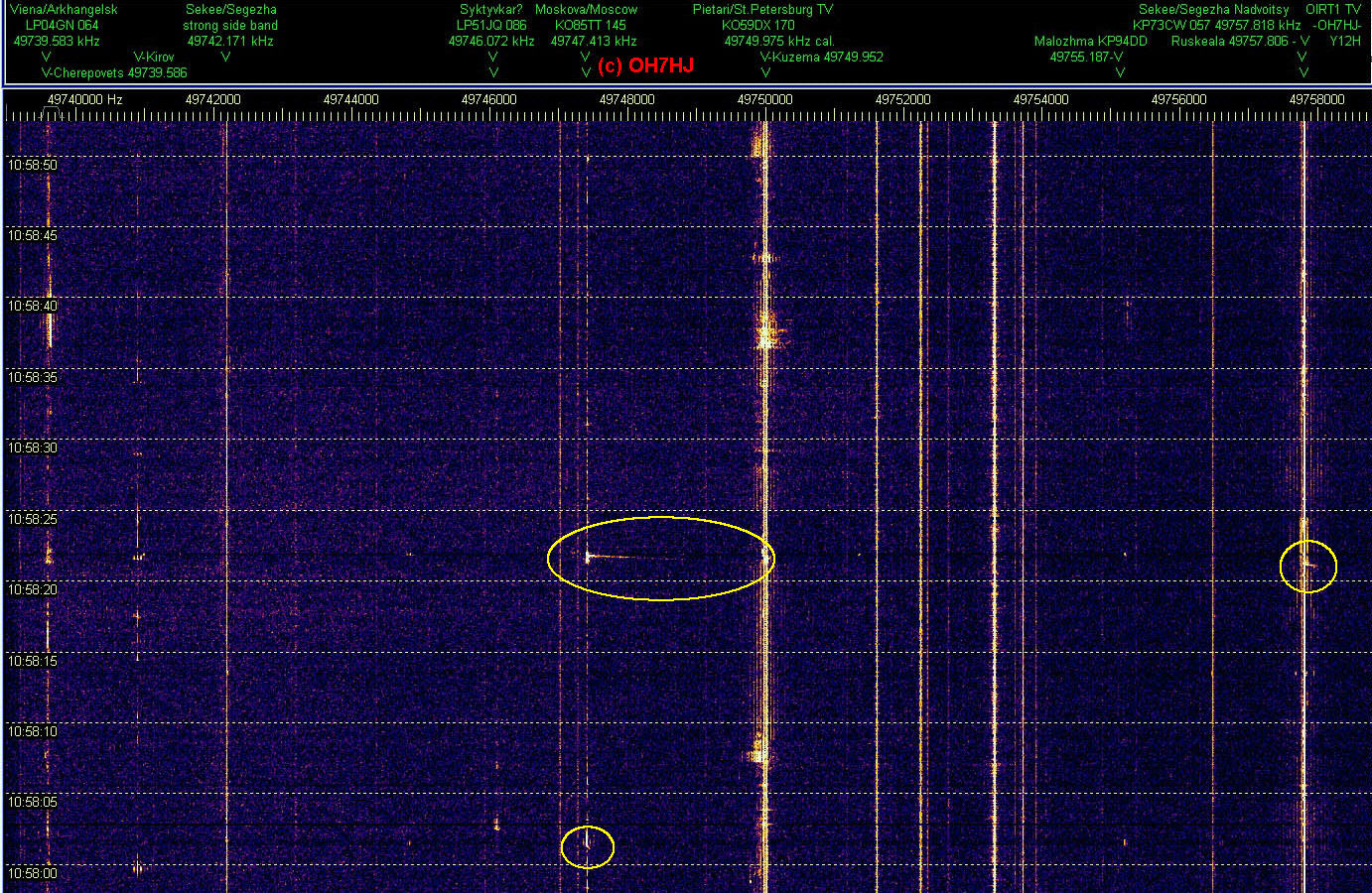
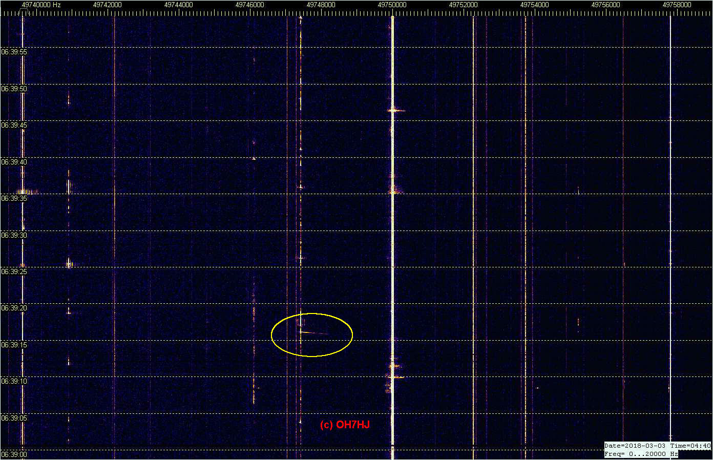
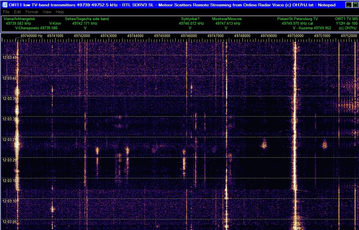
Pic 1: A long meteor scatter (MS) head echo doppler which crosses Moscow TV carrier with abt. 2.5 kHz doppler shift. Visible weaker on St Petersburg and Arkhangelsk/Cherepovets TV carrier freqs, too. The EDS tail appears have ignited before the MS doppler appears. This suggests that this EDS burst may have initiated spontaneusly or by another MS hit and occurs only coincidentally over this unusually long MS doppler.
Pic 2: MS dopplers are usually short and rather rare on St Petersburg TV carrier, maybe either because it is so close and aerial beam is aimed so low that there is not much high meteors that hit between it and rx and low enough. However, here is one that apparently has been large enough to reach down into St Petersburg Tx beam. Strength and length of the MS head echo suggests that it has hit somewhere rather close to SE Finland. The EDS tail of this meteor hit is so strong that it raises TV side bands clearly visible.
Pic 3: A simultaneous MS doppler on St Petersburg and Moscow TV freqs. This one has a very weak EDS tail only.
Pics are cropped from the original set of two Spectrum Lab windows to fit the message thread. Captured from the online radar voice stream from RTL rx with 6-over-6 6m H-yagi array (Y12H) aerial pointing dir 100 degrees. Time labels are Finnish local UTC + 2h. Frequency scale is at top as Hz with usual R1 channel TV Tx’s marked. Please click pics to open and see dopplers.
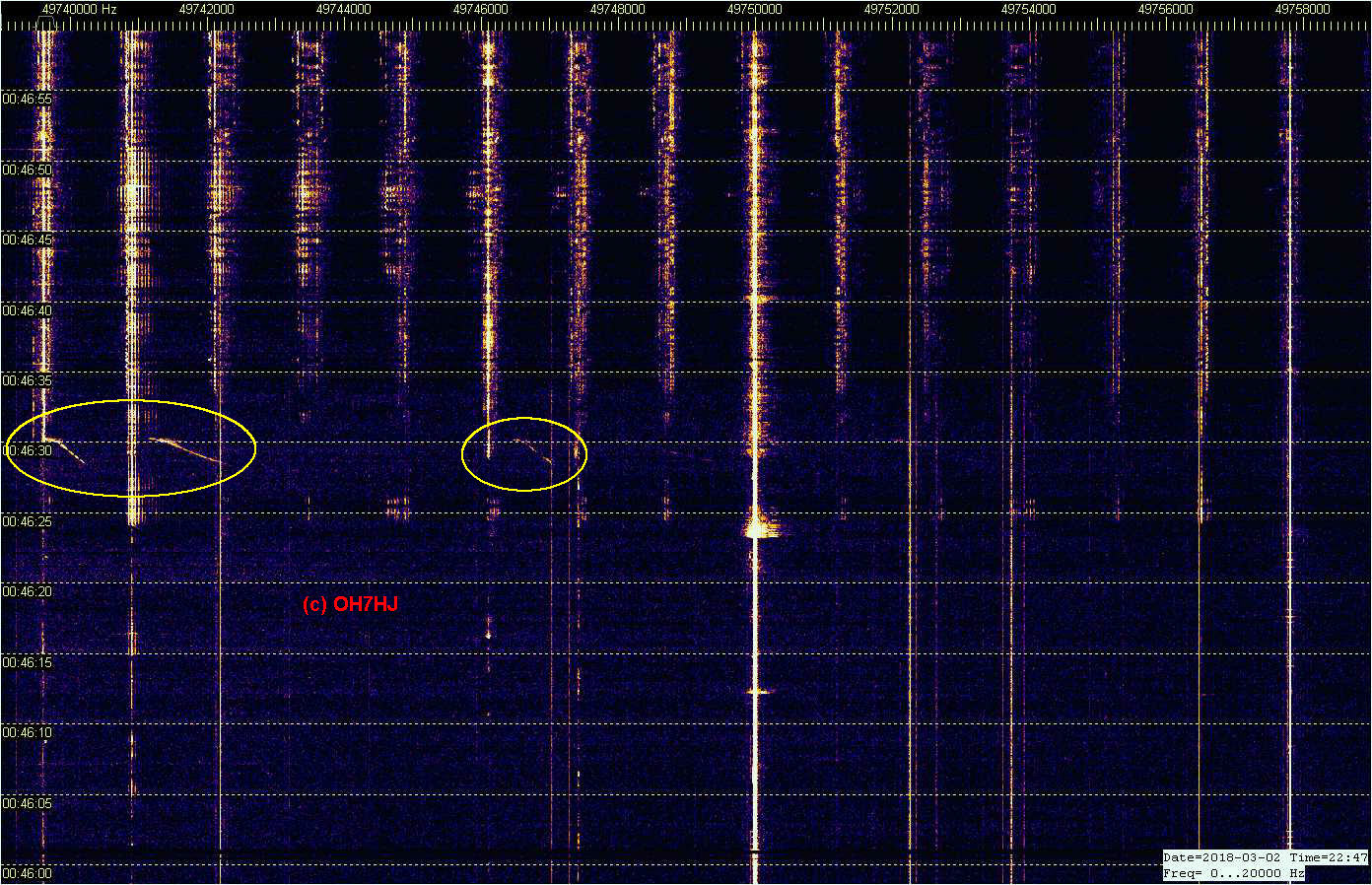
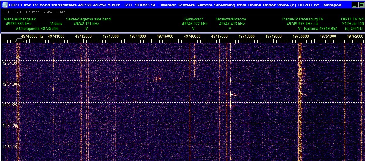
Meteor scatter (MS) head echo (HE) doppler appears on up to six 6m band R1 ch TV Tx freqs simultaneously. There was aurora which made some of these TV carriers ‘fat’ by the aurora typical electric discharge scatter spread noise spectrum.
On St. Petersburg TV carrier there is a faint fifth MS HE doppler right below the strong one. The weak MS doppler is probably caused by meteor trail crossing of one of the small Lake Ladoga area TV Tx carriers like Kotkozero or Suoyarvi. There are also traces of sixth MS doppler on Nyandoma TV freq.
Concluding dy bistatic radar baseline forward scatter effect on Tx’s the likely directions of these MS doppler crossings a possible meteor hit area might be East Finland or Carelia. Meteor scatters like these on multiple Tx frequencies simultaneously could be tracked and located if there were software available for it.
Known TV Tx’s are listed in the scale on top of of each screenshot. Frequency scale is in Hz. Time stamps are FT local plus online streaming delay of abt 10 … 20 s. Recording playback time stamps are arbitrary. Captured and cropped from the online 6m MS multistatic radar voice stream on: maanpuolustus.net/pages/tutka/
50 MHz TV-bandin radiopeilauskokeiluja Spectrum Labin RDF-modella. Ekan liitekuvan oikeanpuoleisissa SL-nauhoissa on kummassakin sama Pietarin jakso, mutta eri antenneista, kuunneltuina koherentiksi muokatun hamssivastaanotinparin kautta. Vasemmanpuoleisella nauhalla näkyy näiden kahden antennin vaihesiirto, joka vastaa kutakin väriä. Eli aallon tulosuunta.
Nauhalta näkyy, että RDF antaa suuntiman periaatteessa spektrin jokaiselle pisteelle. Kun hiirellä osoittaa nauhaa, viereiselle ruudulle ilmestyy spektripisteen taajuuden, ajan ja sinkunvoimakkuuden lisäksi sen suuntima asteina. Pietarin, Kotkozeron ja Suojärven lähetinten tunnettuja suuntia voi käyttää suuntimien kalibroimiseen. Tällainen kahden antennin suuntimo antaa tietenkin myös peilisuuntia.
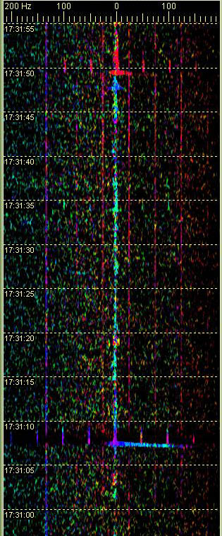
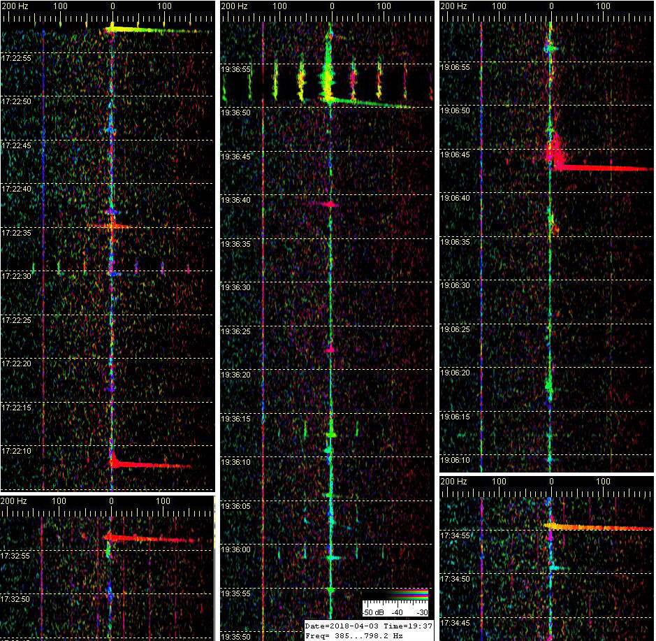
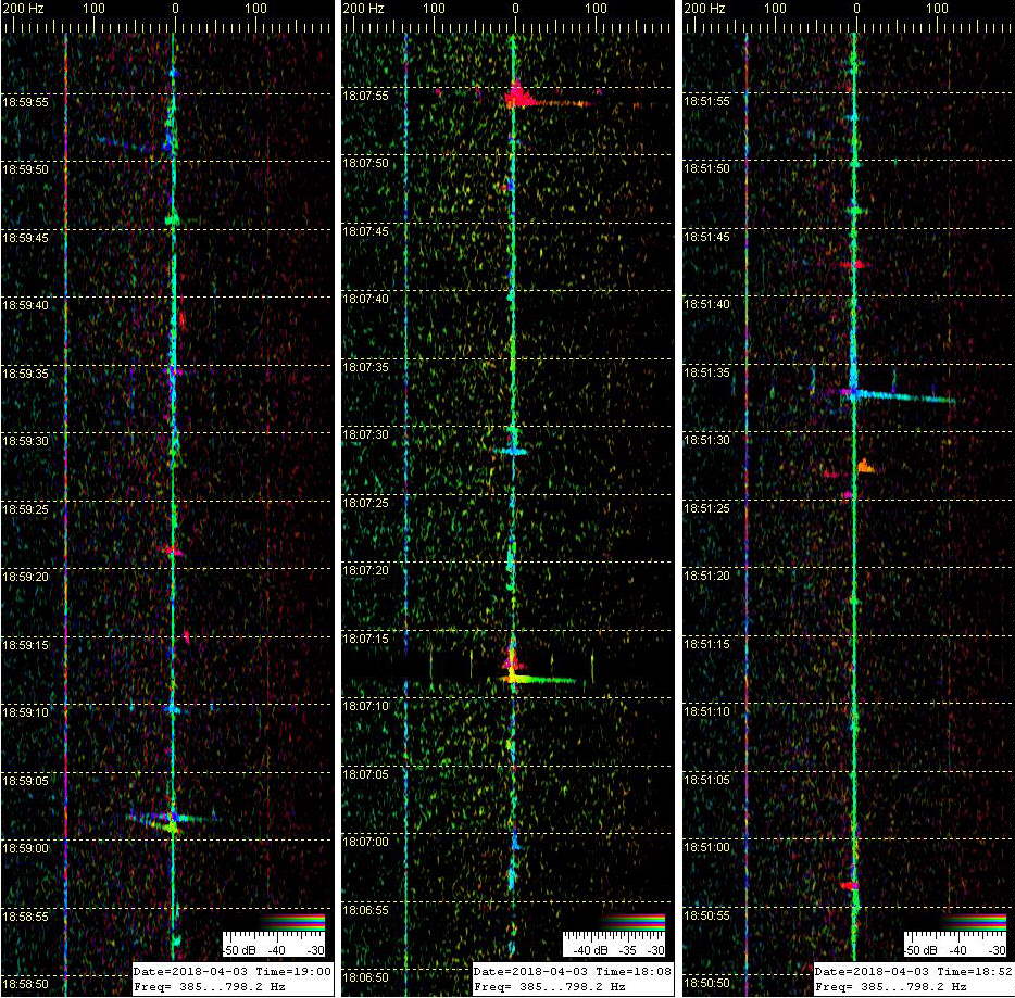
Ensimmäisessä oheiskuvassa lentsikkadopplereiden värit liukuvat suuntiman muuttuessa koneiden lentäessä kuunteluasemani ohi. Lyhytkestoiset luonnonskatterit esiintyvät eri väreissä, niiden aallon saapumissuunnan mukaan. Kolmannen liitekuvan aurorapurskeessa näkyy revontuliskatterin tulosuunnan vaihtelu aurorakohinan värin vaihteluna.
Tästä keskeneräisestäkin koejärjestelystä selvisi, että softa ja vastarien yhdistäminen koherentiksi eli samanvaiheiseksi pariksi näyttävät toimivan. Tämä järjestely ei ole vielä valmis ihan ‘oikeiden’ suuntimien ottamiseen. Tekee vielä liikaa suuntien monikertoja, koska tilapäisantennit ovat keskenään erilaiset, ja liian kaukana toisistaan.
Kunnollisen RDF-antenniparin rakentamista on siis tiedossa, kunhan lumet sallivat. Sitten pitäisi päästä harjoittelemaan TV-lähetinten, meteorien, yläsalamien ym. taivasaaltojen peilausta. Jos pelittää, niin on paljon vaivattomampi ja nopeampi menetelmä suuntia, kuin numeerisesti laskien usean eri noden dopplereista. Toinenkin aseman tietenkin tarvitaan ristisuuntimien ottamista varten.
Started experimenting with radio direction finding (RDF) of MS head echo dopplers and other high sky scatters, inspired by inexpensive radio interferometry setup introduced by PE1ITR.
Only software that I know is available for us hams with interferometry RDF option is the familiar Spectrum Lab. So I joined a pair of FT100 ham receivers together to create a coherent pair of Rx’s needed for a simple two aerial interferometer.
These first pics show examples of 6m band MS HE’s in different colors. Each color is for phase shift between these two signals for separate aerials. In practise, for direction of wave arrival. Two aerial interferometer of course gives mirror directions, too.
Although this experimental arrangement is incomplete by its temporary unpaired aerials that are too far from each other, it seems to confirm that both the SL RDF software and the homebrew coherent rx modification appears to work.
Later when able to build proper RDF pair of aerials - I hope - will be able to provide reliable directions of arrival for natural high sky scatters like these MS and EDS. Still further, will of course need another RDF node for crosslocating these scatters.


