Aircraft Scatter - Lentokoneheijastus ja sen doppleri.

AS doppler pics series continued from previous message. Aircraft coming from north is flying lower which makes its doppler weaker.

Previous observation reports:

Arkhangelsk TV AS dopplers - 458 km, part 1 - Aircraft Scatter - Lentokoneheijastus ja sen doppleri.
Arkhangelsk TV AS dopplers - 426 km, part 2 - posting.php?mode=reply&f=21&t=295#pr2382
Arkhangelsk TV AS dopplers - 416 km, part 3 - Kerhon kaluston lainausvihko
Arkhangelsk TV AS dopplers - transverse crossing 1 - Kerhon kaluston lainausvihko

  • Juha
    2017-10-04-0248 FT - PF playback - Y6E 060 Arkhangelsk TV - UT577 B737 alt 10973 m doppler fadeout location - Next plane SU1323 B738 10058 m (c) OH7HJ.JPG
    2017-10-04-0251 FT - PF playback - Y6E 060 Arkhangelsk TV - Next plane SU1323 B738 10058 m at doppler crossing location (c) OH7HJ.JPG

These are aircraft scatter dopplers on Nyandoma TV Tx carrier east of Lake Onega (Äänisjärvi). Nyandoma is supposed to have a medium power TV transmitter with ERP of 46 kW.

There were more similar dopplers in Nyandoma spectrum strips but because many domestic flights do not use locating ADS-B transponders these flights are not visible on online radar servers like PF and FR24 they could not be identified.

Rx aerial is a 6 over 6 element 6m band yagi array (Y12H) pointing at dir 100. Time stamps are Finnish local and time ticks at spectrum strip are 5 minutes apart. Doppler archive with copies of these spectrum strips is arranged by date and local time at: maanpuolustus.net/muut/tutka/kuvat/

Previous: AS dopplers on Nyandoma TV carrier - 395 km- viewtopic.php?f=21&t=295&start=150#p2370

Luonnolliset radioaaltojen hajaspektriheijastukset yläsalamoista saavat joskus hupaisia muotoja. ‘Kovista’ ja ‘kylmistä’ keinotekoisista kohteista, kuten lentokoneista heijastuvat radioaallot näkyvät yhtä kapeina dopplerjuovina, kuin niiden lähetinkin. Luonnollisista sähköisistä ‘kuumista’ ja ‘pehmeistä’ lyhytaikaisia plasma- ja ionipilviä muodostavista sähkönpurkausilmiöistä heijastuvien aaltojen tunnusmerkki on hajaspektri, eli kaiku ‘leviää’ enemmän tai vähemmän. Joskus kohinana, joskus kuvien kaltaisina haarautuvina kiharoina tai ‘dopplerkoukkuina’.

Nämä sähköskatterit on tallennettu Cherepovetsin TV:n kantoaaltotaajuudella n. 49739,583 kHz. Lähekkäisellä taajuudella on myös Arkangelin eli Vienan TV. Nauhoilla näkyy myös näitä kaukaisempien TV-lähetteiden kantoaaltojen tai sivunauhojen heijastuksia. Viistoviivat nauhoilla ovat lentsikkadopplereita Cherepovetsin TV-sivunauhakopioineen.

Otoksissa Spectrum Lab -softan taajuusasteikko yläreunassa on hertseinä, Cherepovetsin TV-kantoaallon kohta likimain nollana, muutaman hertsin ryömintätoleranssin puitteissa. Aikaleimat vasemmalla ovat Suomen aikaa. Radiospektrinauhan liikesuunta on ylhäältä alas. Vastaanotin on tavallinen halpa RTL-SDR-tikku kuuntelemassa 50 MHz 4-el ympärisäteilevää dipolimattoantennia (D4H) radiosoftan HDSDR ja virtuaaliäänikaapelin kautta.

Linkkejä taivasheijastuksiin ja yläsalamiin

Electric Discharge Explanation of Nasa ‘Aurora Arrow’ Photo - viewtopic.php?f=21&t=295&start=150#p2374
Already somewhat known spreading and dividing natural high altitude electric discharges are ‘sprite’ lightnings. Sprite photos by Thomas Ashcraft: heliotown.com/Catalog_Transi … vents.html

“Sprites, Elves and Intense Lightning Discharges”, Nato Science Series II: books.google.fi/books?id=XagIZh … es&f=false
Upper-atmospheric lightning: en.wikipedia.org/wiki/Upper-atm … _lightning
The Manastash Ridge radar: A passive bistatic radar for upper atmospheric radio science - onlinelibrary.wiley.com/doi/10.1 … S02454/pdf

EDS - Yläsalamat aiheuttavat radioheijastuksia: Aircraft Scatter - Lentokoneheijastus ja sen doppleri.
Sähkönpurkausheijastus EDS - Electric Discharge Scatter: Aircraft Scatter - Lentokoneheijastus ja sen doppleri.
Yläsalamapurkauksen synnyttämä ukkos-Es-keli: Aircraft Scatter - Lentokoneheijastus ja sen doppleri.

‘Doppler hooks’ - ‘Dopplerkoukkuja’ ‏Moskovan, Arkangelin ja Pietarin TV-jaksoilla:
Osa 1: viewtopic.php?f=21&t=295&start=100#p1893
Osa 2: Aircraft Scatter - Lentokoneheijastus ja sen doppleri.
Osa 3: viewtopic.php?f=21&t=295&start=110#p1901
Osa 4: viewtopic.php?f=21&t=295&start=110#p1903
Osa 5: Aircraft Scatter - Lentokoneheijastus ja sen doppleri.

Online bistatic radar demo listening to R1 TV channel carriers at maanpuolustus.net/muut/tutka/kuvat/

Briefly in English: High sky radio scatters sometimes plot curious patterns on these R2 TV channel spectrum strips. Here are a few examples of these natural dividing spread spectrum scatters.


Kirkkaana tulipallona maiseman valaiseva tähdenlento havaittiin Lapissa illalla 16.11.2017. Ursan asiantuntijan mukaan tähdenlennon arvioidaan pudottaneen kymmeniä kiloja, jollei jopa satakunta kiloa meteoriittikiviä Inarinjärven etelä- tai kaakkoispuolelle. Tässä 50 MHz bandin monipaikkatutkan tallenteessa näkyy ehdokas tulipallon tutkajäljeksi ympyröitynä, lähinnä sopivan tapahtuma-ajan perusteella.

Jannelta sain tulipallon tarkan alkuajan 18:40:15.241, joka on peräisin Panu Lahtisen Ivalossa olevasta allsky-kamerasta. Kiitos! Tulipallon tarkka syttymisaika näyttäisi sattuvan tutkanauhan lukematarkkuuden puitteissa yhteen tämän tutkatallenteen kanssa. Spectrum Labin hitaalta nauhalta pystyy ajan arvioimaan noin 10 sekunnin tarkkuudella.

Vaikka tutkakaiku näyttää hyvin samanaikaiselta, se voi silti olla jokin tästä tähdenlennosta riippumattomista lukuisista korkean taivaan sähkönpurkausheijastuksista (EDS, Electric Discharge Scatter), joita vastaanotin havaitsee jatkuvasti tällä Arkangelin TV:n taajuudella muutaman minuutin välein. Nauha on tallennettu on pohjoiskoilliseen katsovalta 6-elementtiseltä PA50-6-6 -jagiantennilta HDSDR- ja Spectrum Lab -softilla Arkangelin TV:n kantoaallon taajuutta 49739,586 kHz kuuntelevalta RTL-vastaanottimelta. Nauhan aikaleimat ovat Suomen aikaa.

Liitteet ja linkit:

Video tulipallosta: m.facebook.com/story.php?story_ … cation=ufi

Uutisartikkeleita: mtv.fi/uutiset/kotimaa/arti … gs.JyxwLmQ

Silminnäkijäkomentteja: satakunnankansa.fi/kotimaa/ … 200542207/

Jannen kertoma alkuaika: facebook.com/groups/luonnon … 22R9%22%7D

Ursan Taivaanvahtiin ilmoitetut havaintoajat vaihtelevat n. 18.35 … 18.40 välillä: taivaanvahti.fi/observations … _id/desc/0

Monipaikkatutkan online demonäyttö: maanpuolustus.net/pages/tutka/

Liitekuva tutkanauhasta: LP HDSDR Y6E 030 Arkhangelsk TV © OH7HJ - 2017-11-16-1800 - Bolide in Lapland at 184015 FT - Unknown radar trace at abt 184010 FT.jpg

T: - Juha -
Source pic LP HDSDR Y6E 030 Arkhangelsk TV (c) OH7HJ - 2017-11-16-1800 - HMO - Bolide in Lapland abt 1840 FT - Unknown trace at abt 184010.jpg
LP HDSDR Y6E 030 Arkhangelsk TV (c) OH7HJ - 2017-11-16-1800 - Bolide in Lapland at 184015 FT - Unknown radar trace at abt 184010 FT.jpg

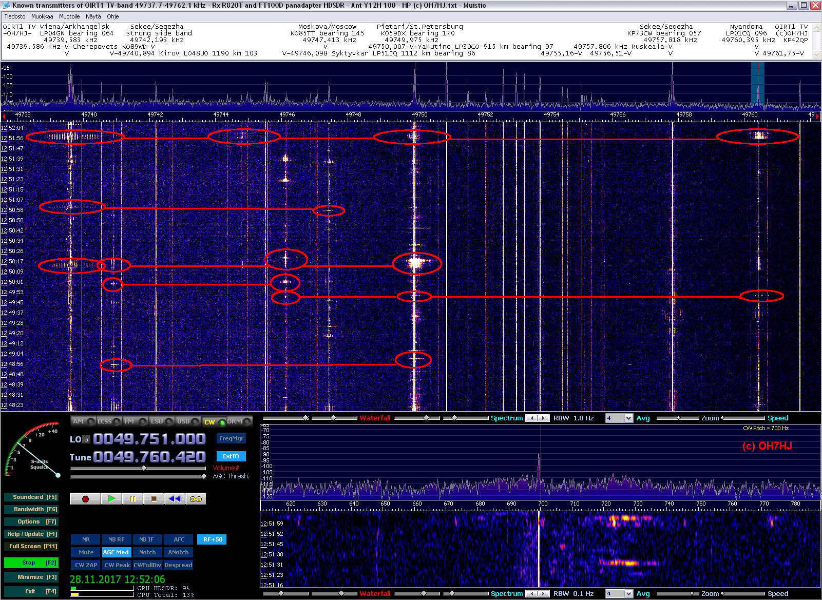
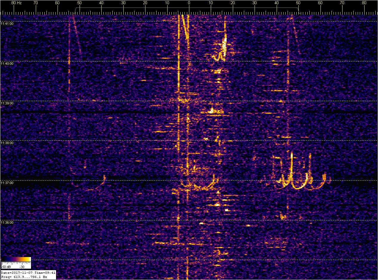
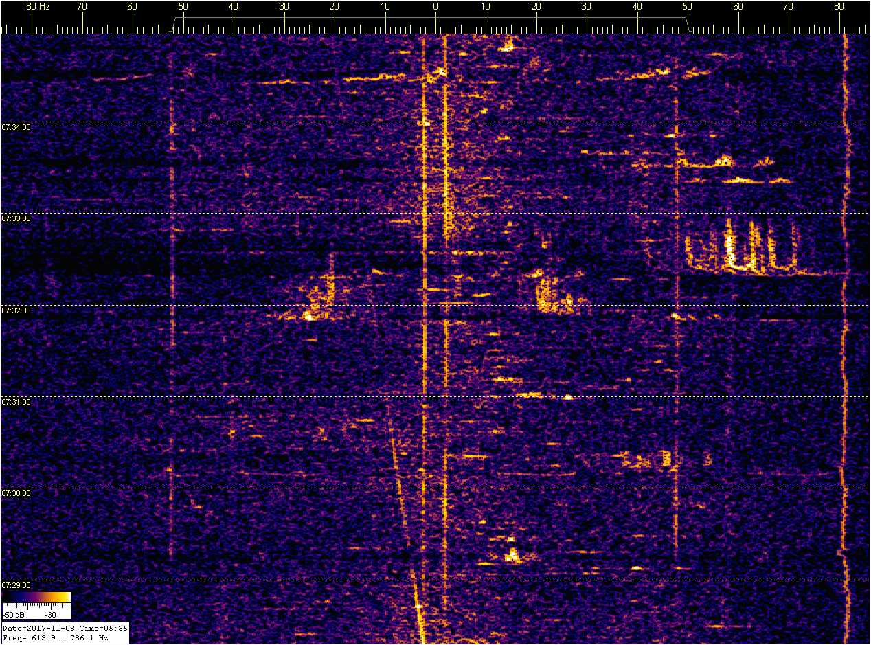
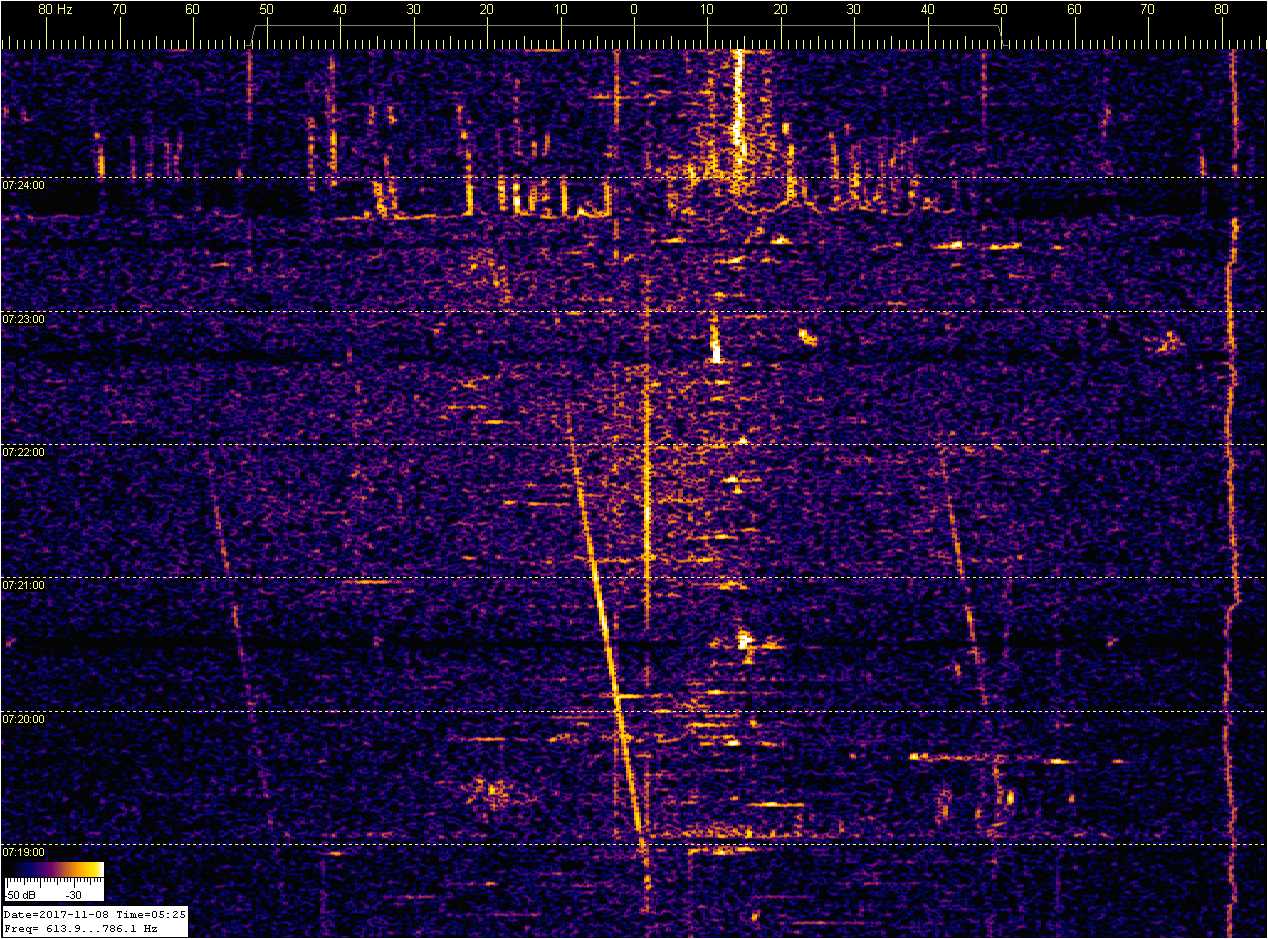
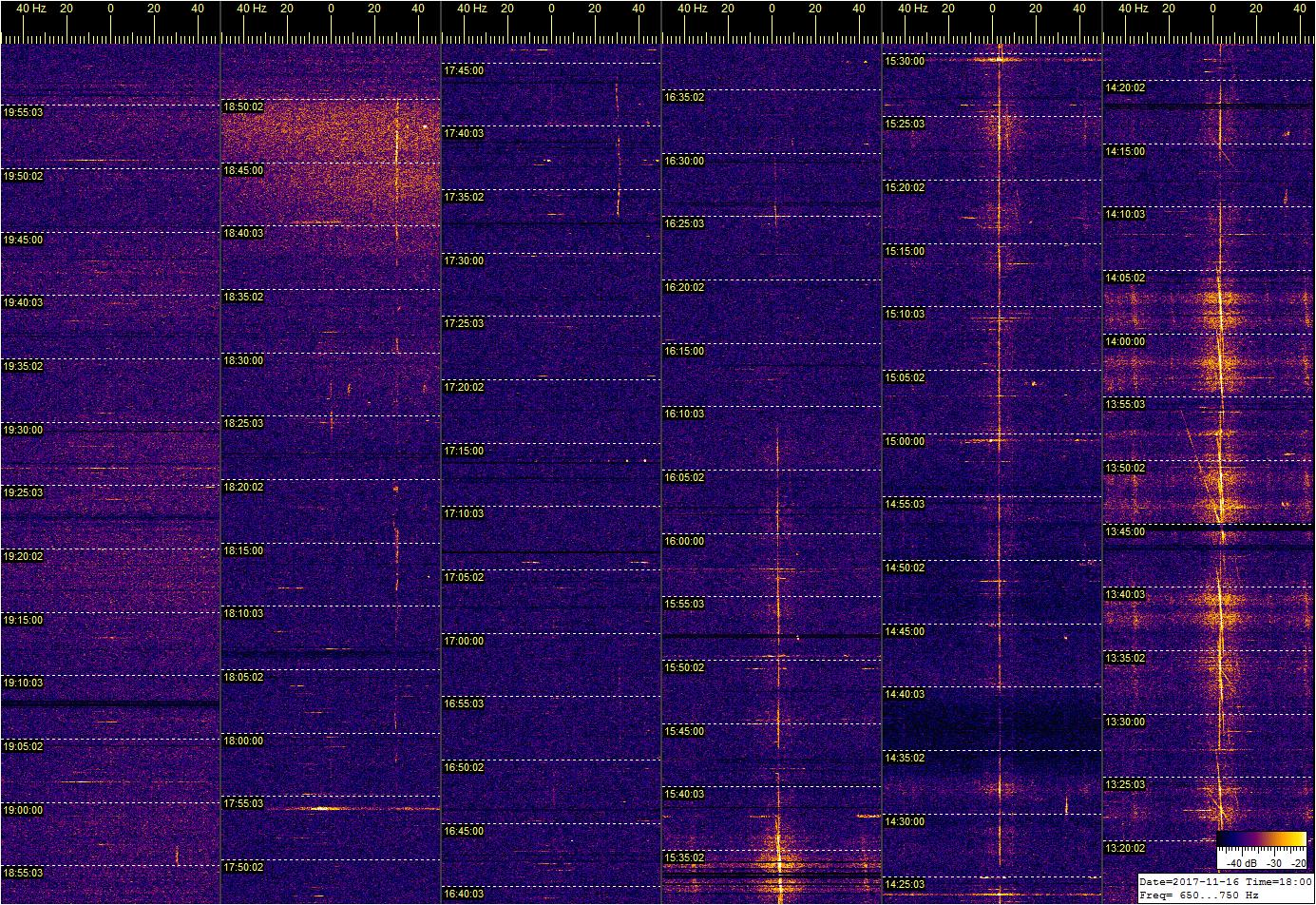
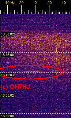
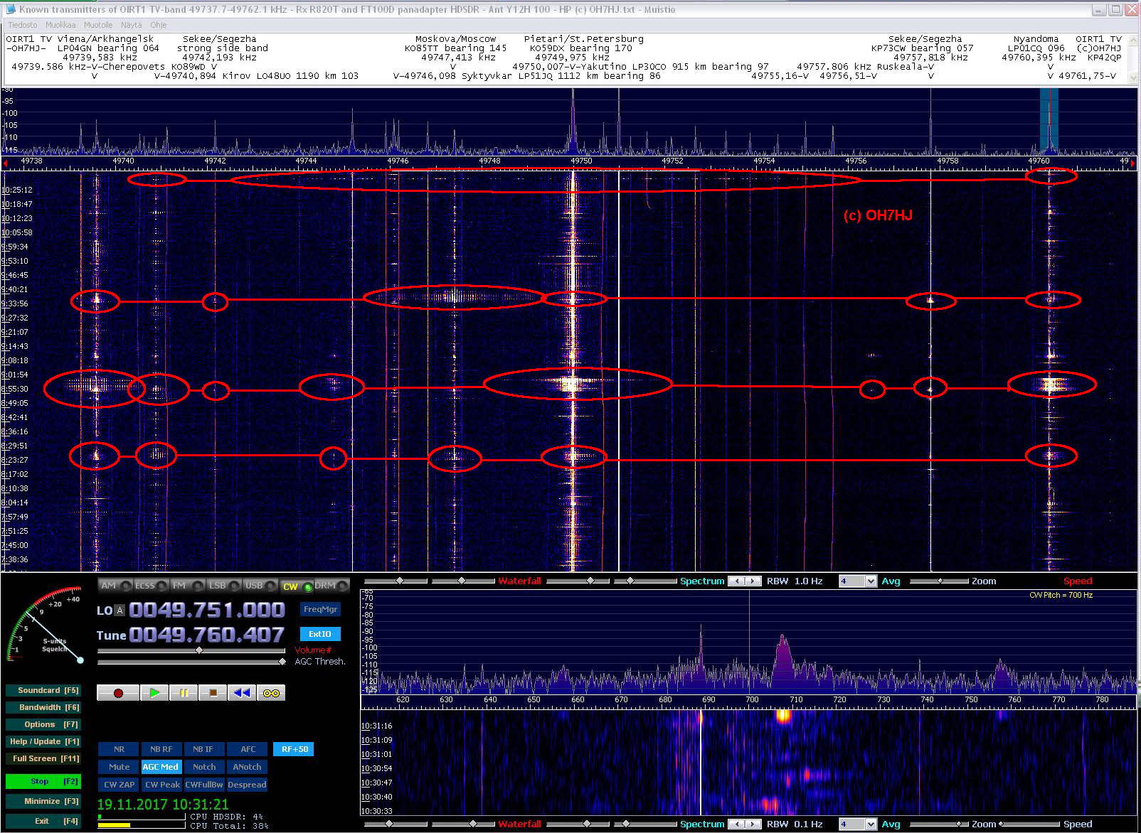
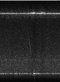
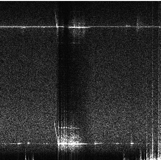
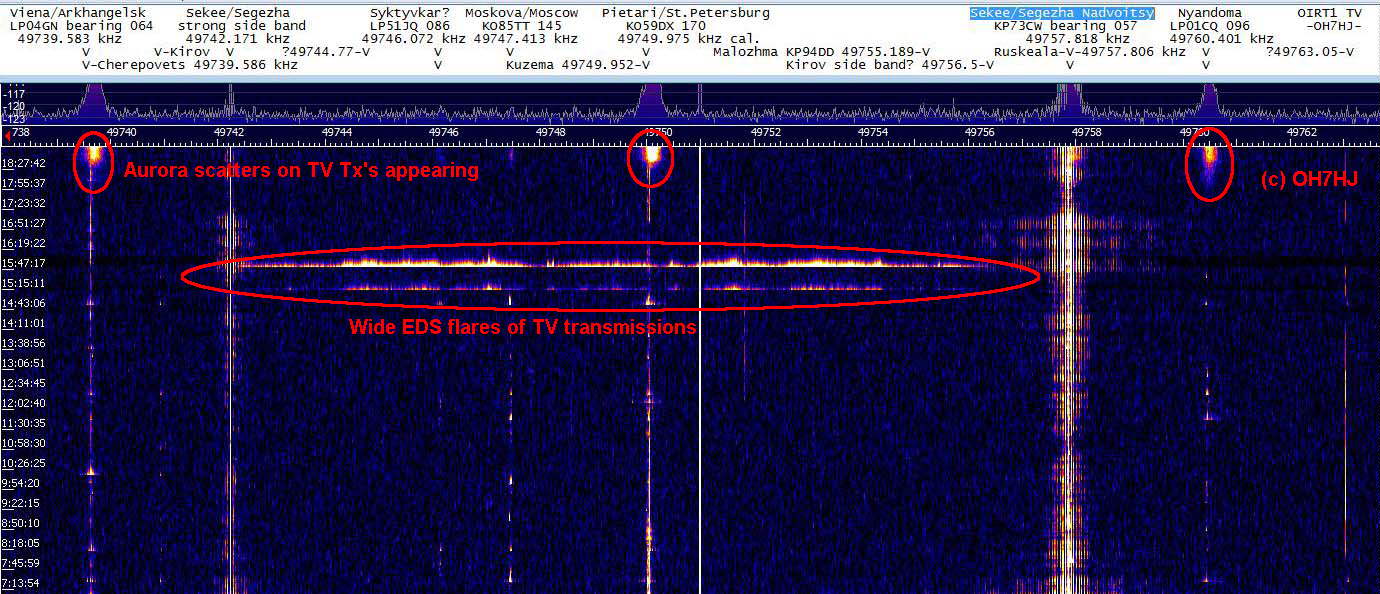
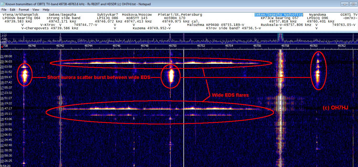
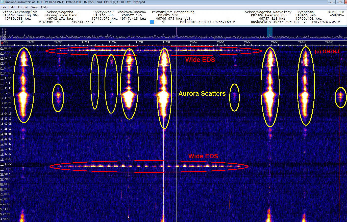
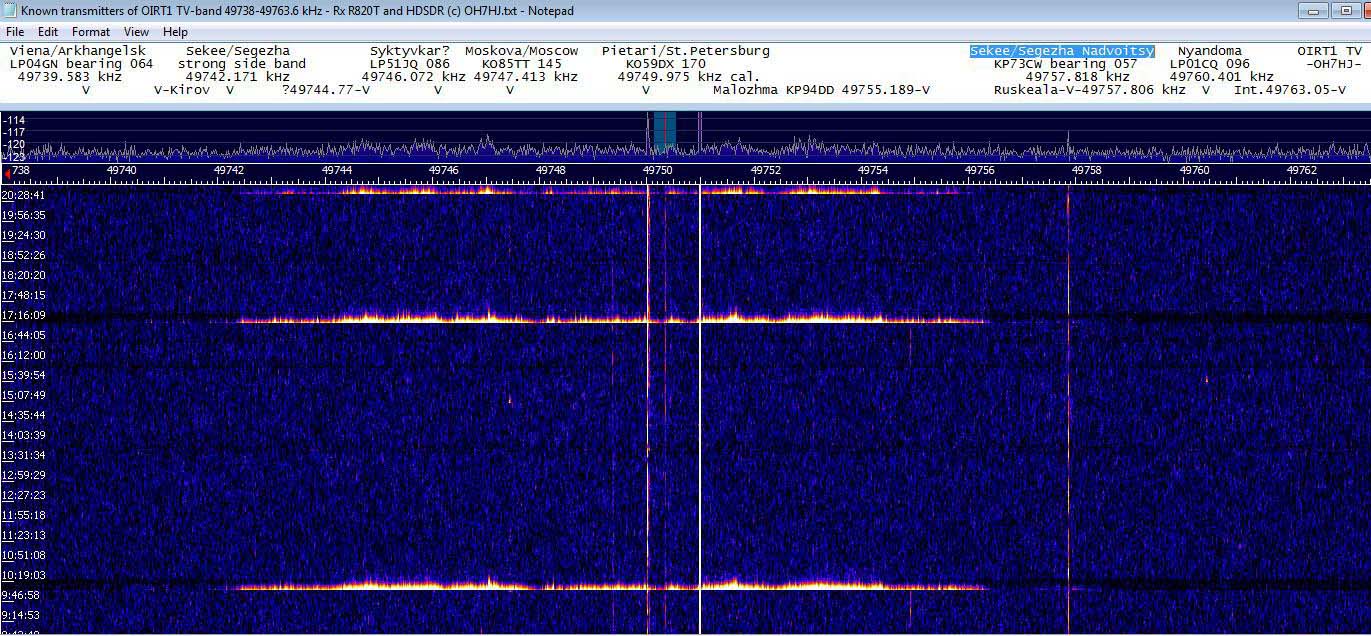
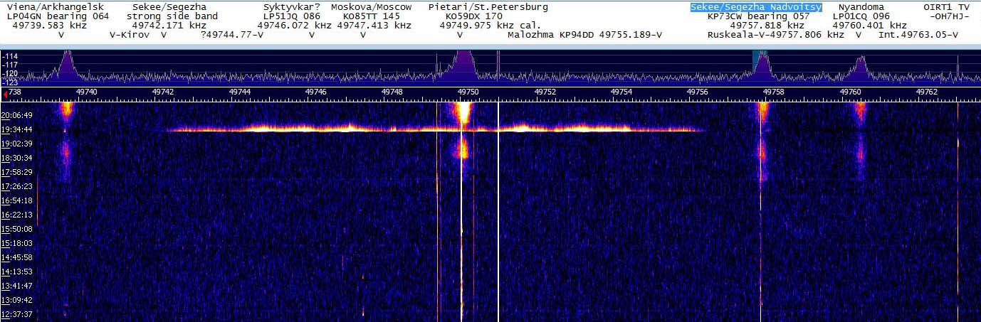
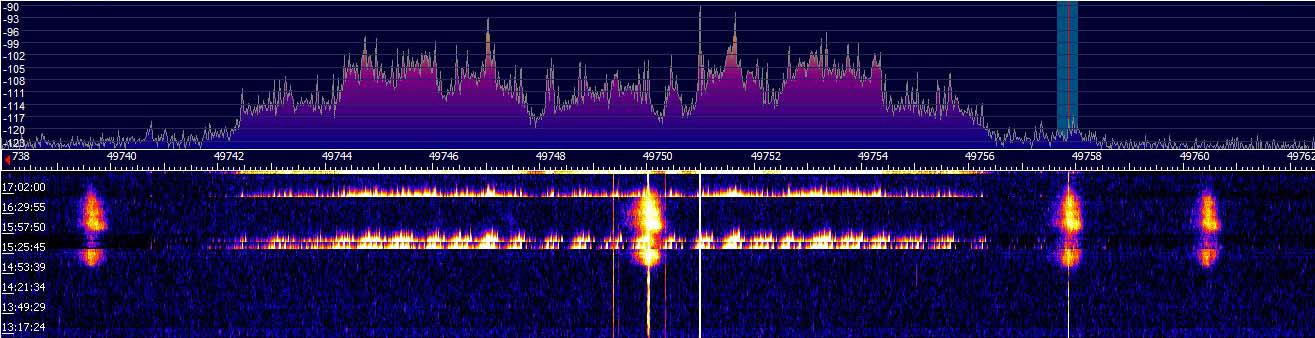
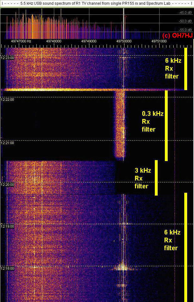
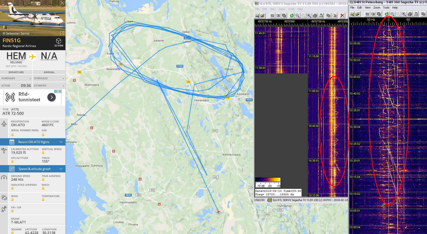
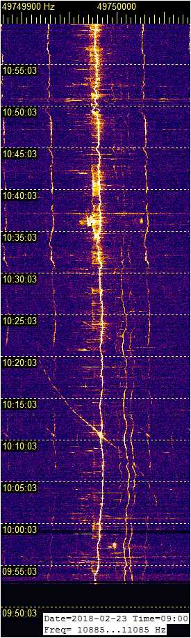
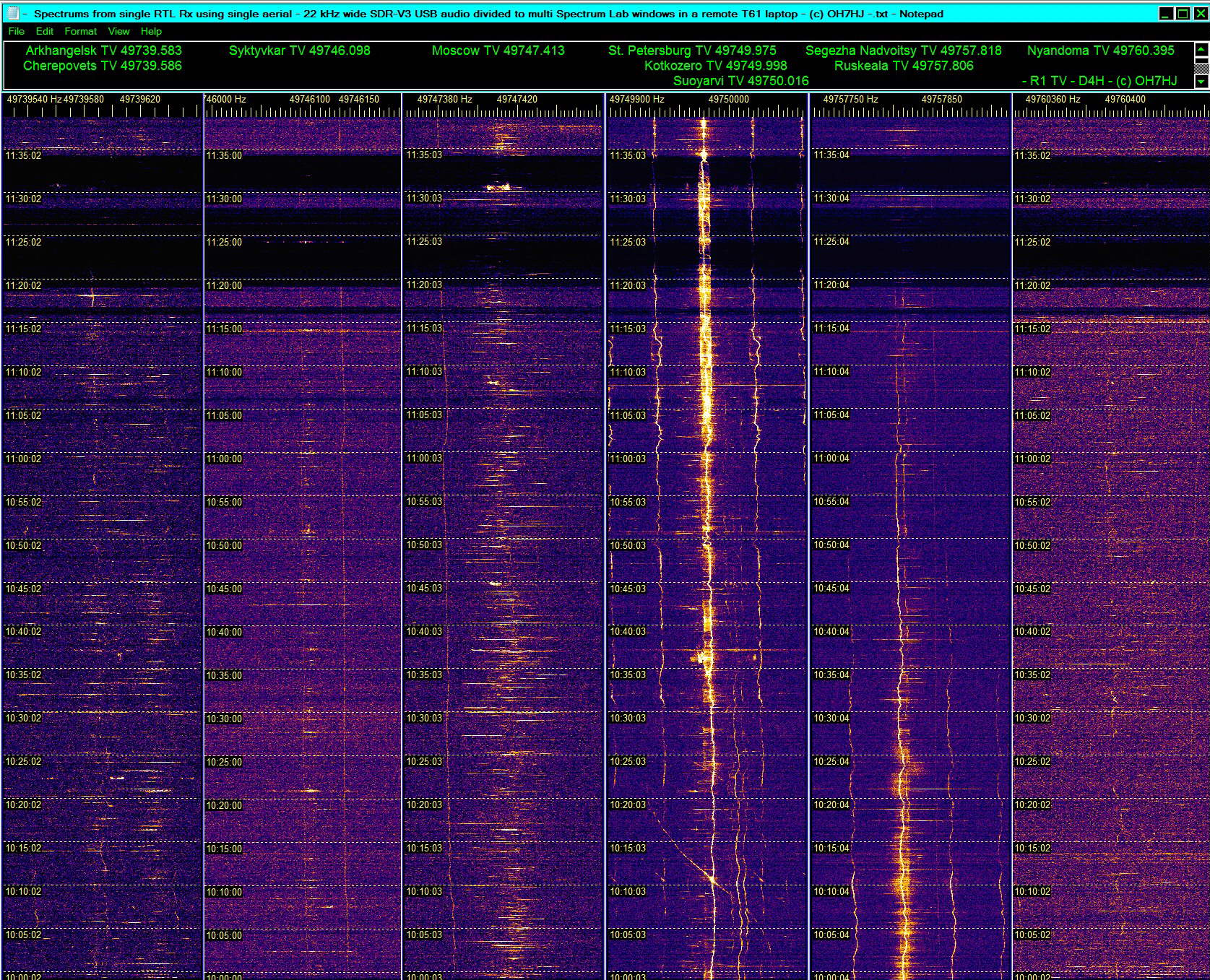
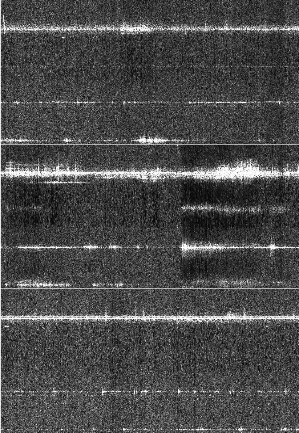
Näihin HDSDR-softaradiolla havaittuihin tyypillisiin spektreihin 6m TV-bandin R1-kanavalta merkkasin ympyröiden ja viivoilla yhdistäen joitakin esimerkkejä samanaikaisista luonnollisista heijastuksista, jotka ovat yhtaikaisia eri TV-lähetinten jaksoilla. Samanaikaiset luonnolliset radioskatterit näkyvät useina erilaisina yhdistelminä eri TV-lähetinten taajuuksilla. Koska radioheijastukset ovat voimakkaimpia lähetinten suunnilla esiintyvistä korkean taivaan kohteista, näiden samanaikaisista yhdistelmistä voi arvioida korkean taivaan heijastusten aiheuttajien summittaista tapahtumissuuntaa TV-lähetinten suuntiin vertaamalla.

Esimerkkiskattereden alussa ei näy meteoriheijastusten tuntomerkkiä, meteorivanan nopean lineaarisen liikkeen head-echo-doppleria, joten ne lienevät tavanomaisia spontaanisti syttyneiden luonnollisten korkean taivaan sähkönpurkausten radioheijastuksia (Electric Discharge Scatter EDS). Tällaisia sähkönpurkausheijastuksia näkyy ala-VHF-bandeilla jokseenkin jatkuvasti, kun taas meteoridopplerit (MS) ovat varsin harvinaisia.

Pitkäaikainen seuraaja saattaisi havaita spontaanien luonnonskattereiden seasta satunnaisia nopeita meteoridopplereita, ja käyttää niiden voimakkuusvertailua meteorivanan tapahtumasuunnan arvioimiseen tunnettujen TV-lähetinten suuntien perusteella. Vielä tarkemmin heijastusten radiosuuntiminen onnistuu tietenkin interferometrialla, jos käytössä on koherentti tuplavastari ja -antenni.

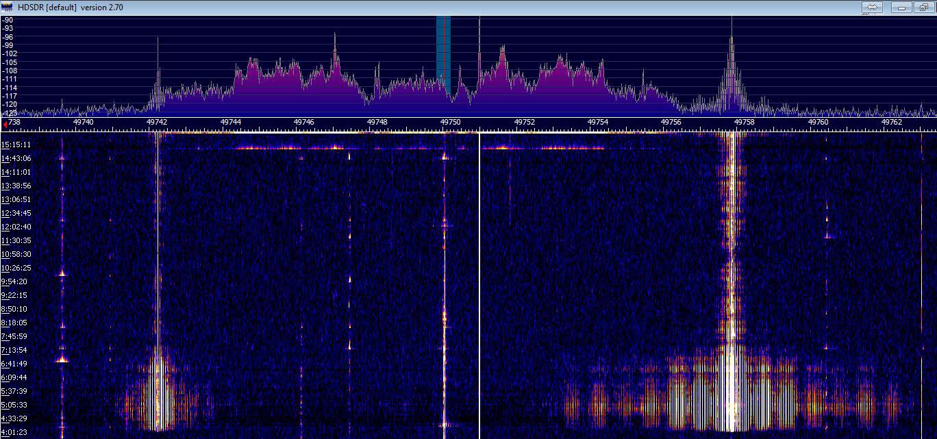
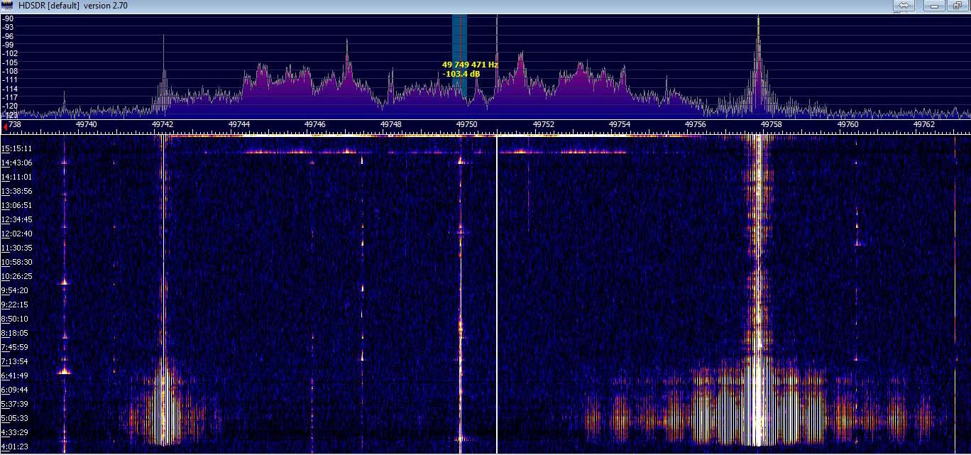
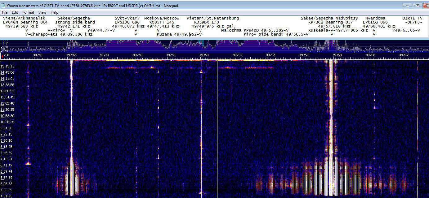
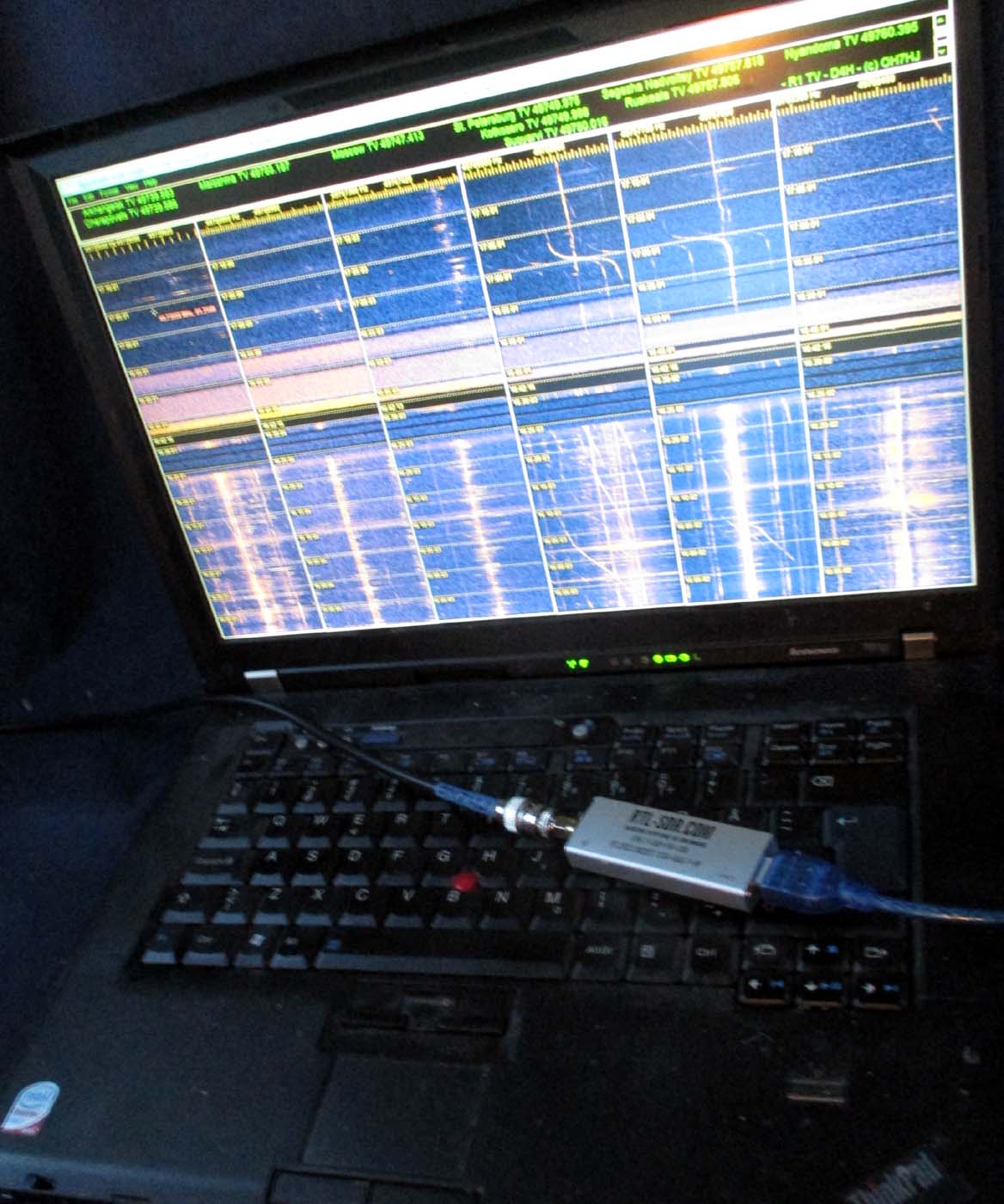
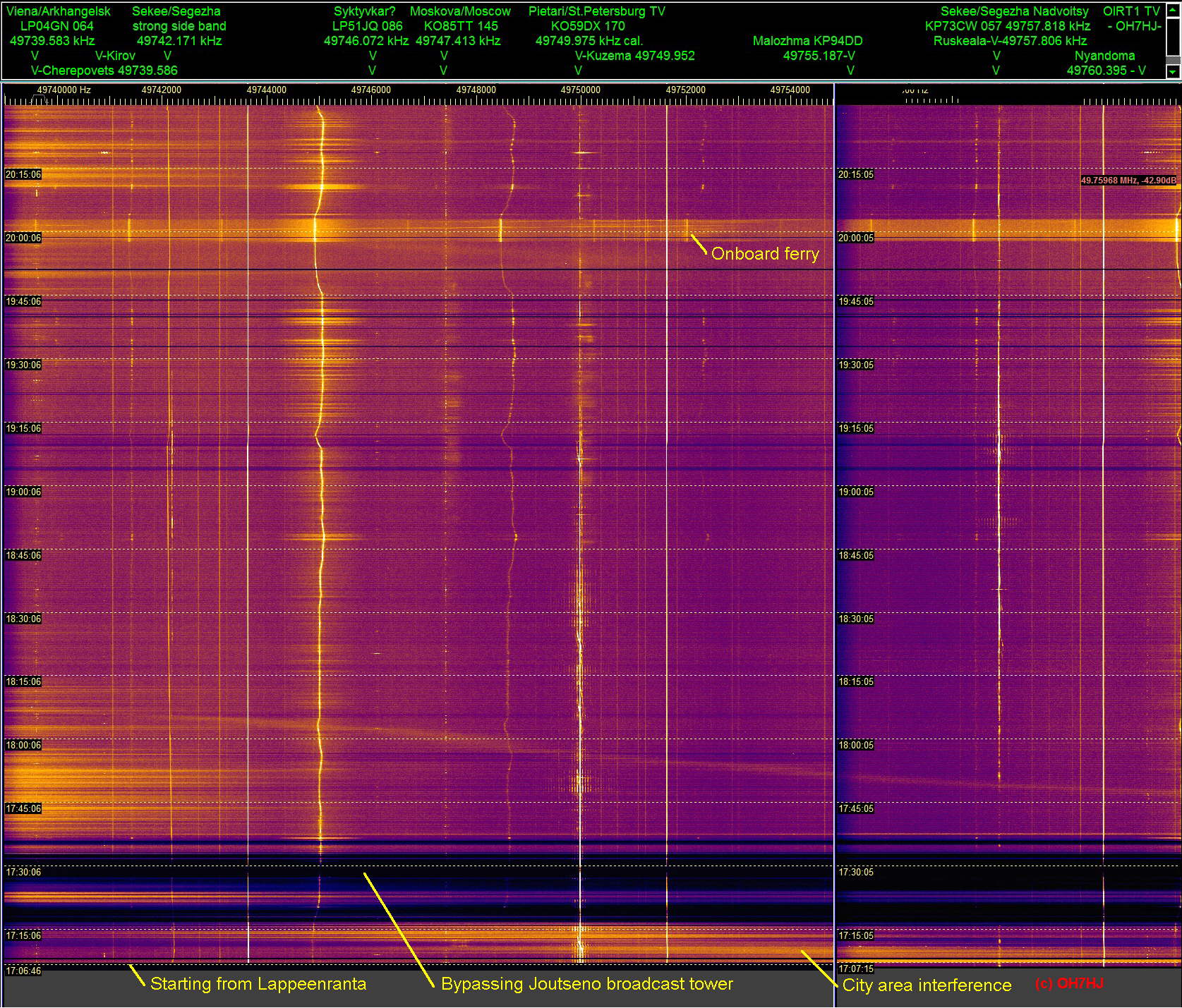
Tunnistetut parhaiten näkyvät TV-lähettimet taajuuksineen, lokaattoreineen ja karttasuuntineen on merkitty spektrikuvan yläreunan asteikolle. Muita etäisiä TV-lähettimiä, joiden luonnollisia heijastuksia nauhoilla myös satunnaisesti näkyy, on toki paljon näitä merkittyjä enemmän. Taajuusasteikko yläspektrin ja vesiputouksen välissä on kilohertseinä (kHz). Aikaleimat vasemmassa reunassa ovat Suomen aikaa, ja päiväys sekä vastaanottosetuppi on merkitty kunkin otoksen tiedostonimeen.

Linkkejä

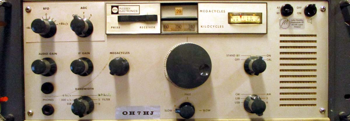
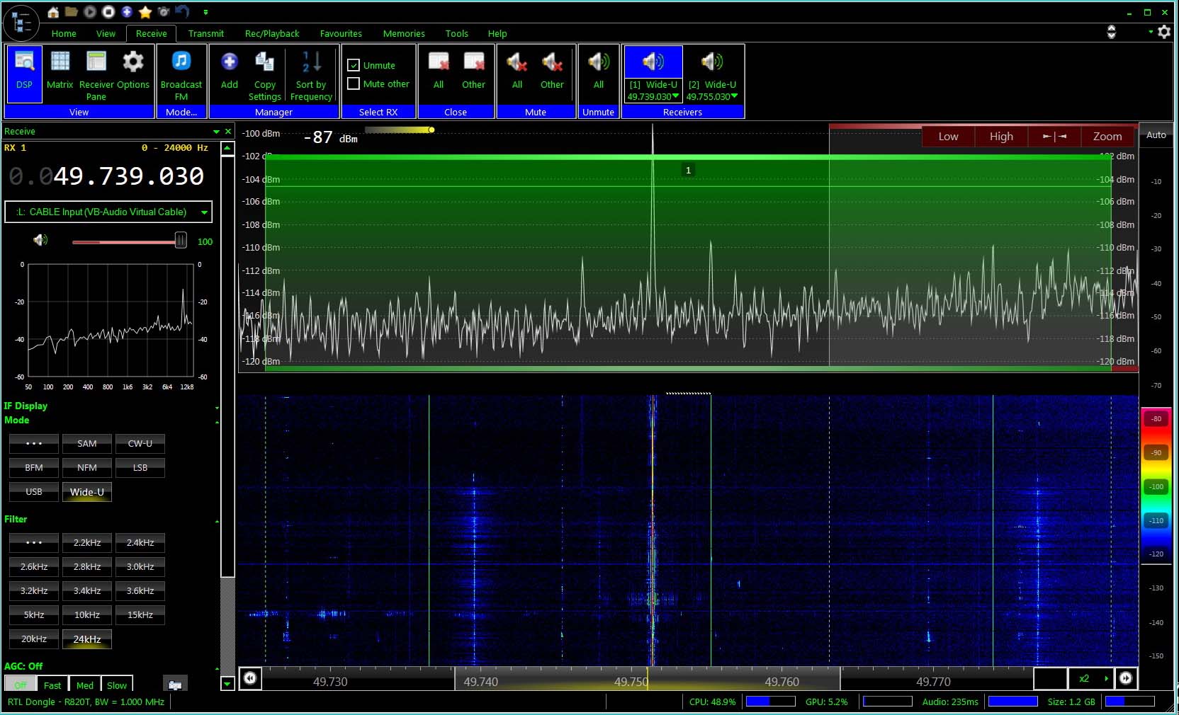
Oheiset esimerkkiotokset on kopitettu hamssivastarin välitaajuutta kuuntelevalla RTL-SDR-tikulla tällä itään katsovalla jagikaksikolla: viewtopic.php?f=21&t=599&start=30#p1853

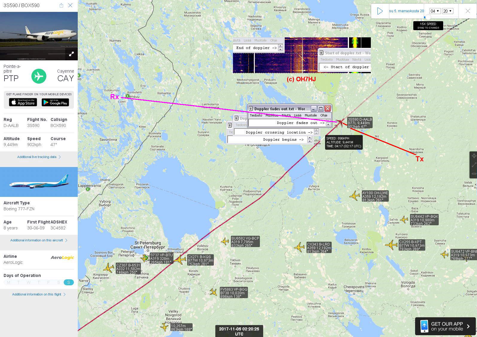
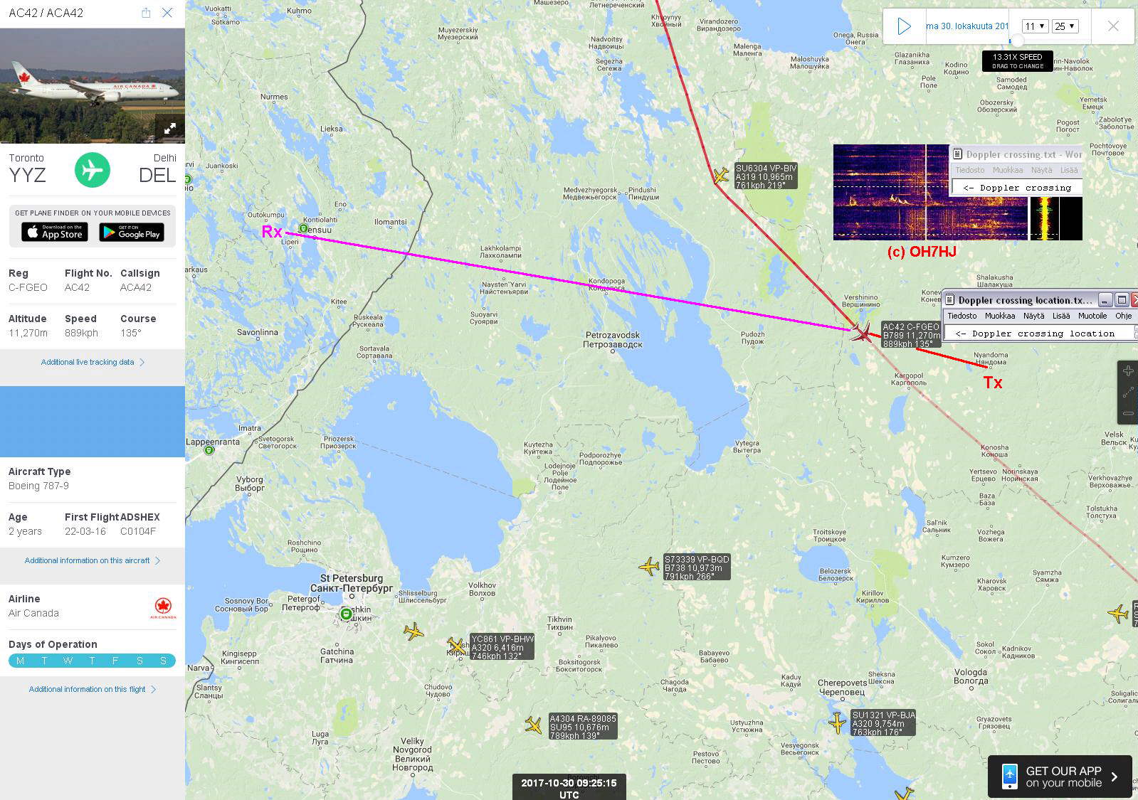
Sekä luonnollisia radioheijastuksia, että lentsikkadopplereita voi käyttää myös kaksisuuntaiseen kusoiluun. Tässä yksi softa lentsikkaskatteriyhteyksien harrastajille: AirScout is a Software for Aircraft Scatter Prediction - airscout.eu/

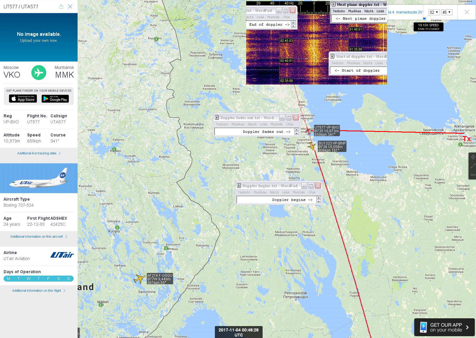
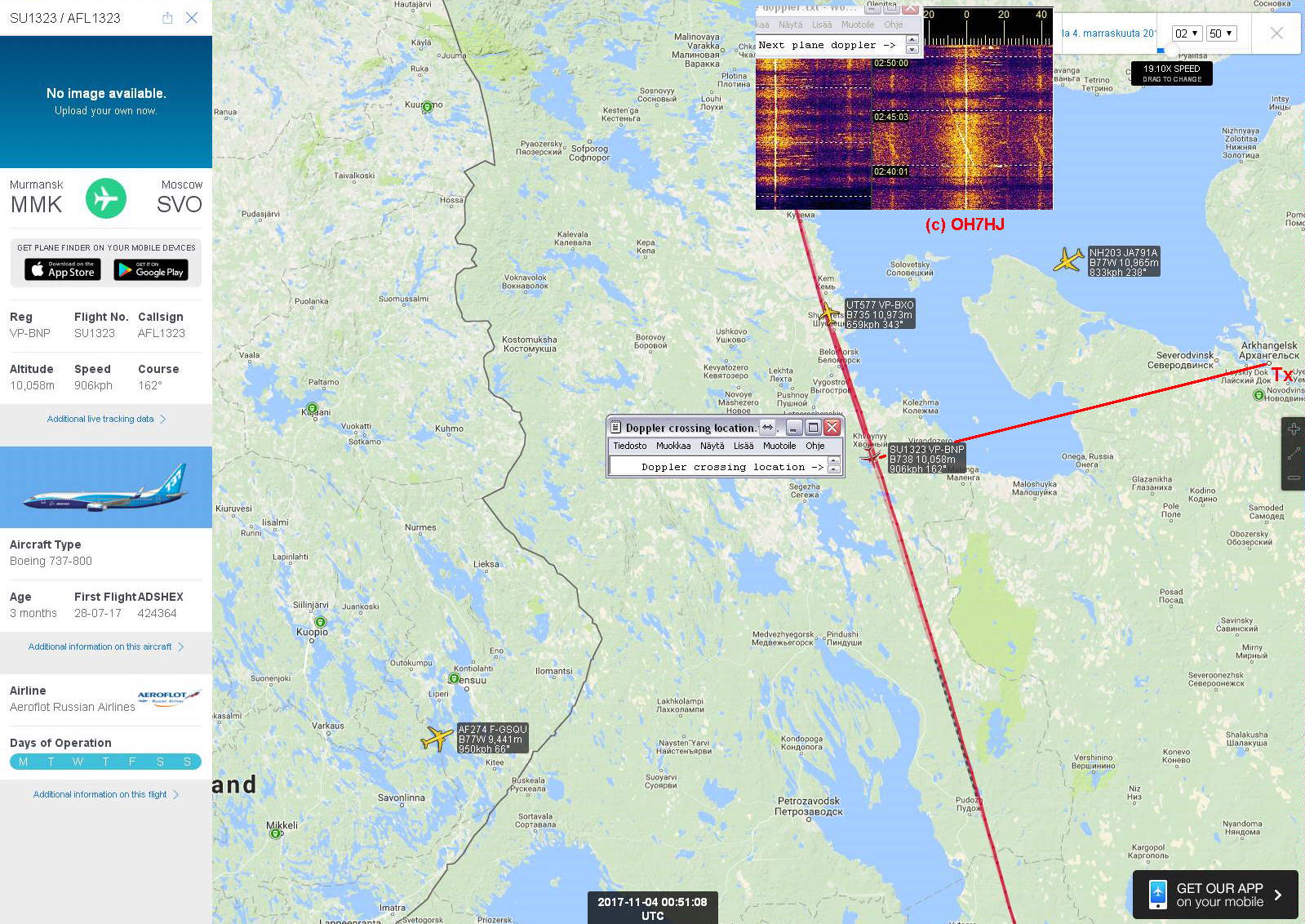
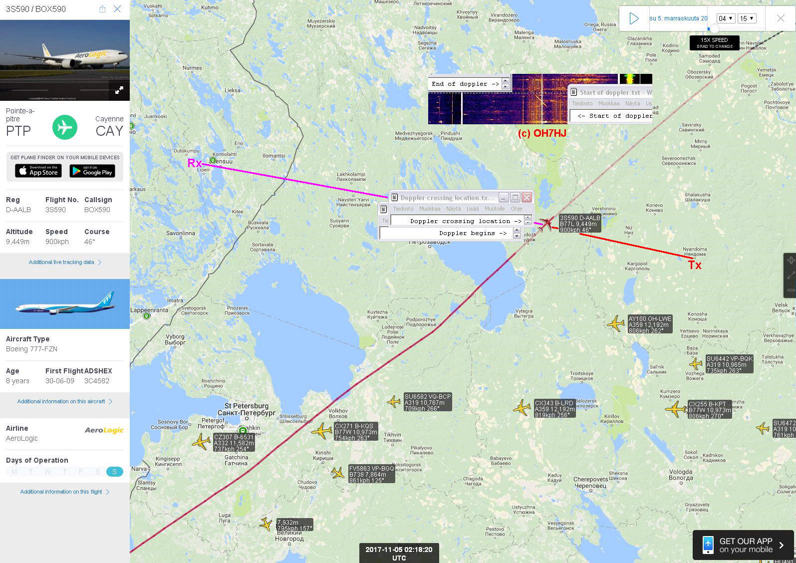
Lentsikkaheijastusten käyttäminen tuntemattomien radiolähetinten suuntimiseen (Aircraft Scatter Direction Finding, ASDF) - Aircraft Scatter - Lentokoneheijastus ja sen doppleri.

Radiosuuntiminen kahden tai useamman antennin ja koherentin vastaanottimen interferometrialla: Simple Interferometer for Radio Direction Finding (RDF) - itr-datanet.com/~pe1itr/sate … ometer.htm

[b]In English:

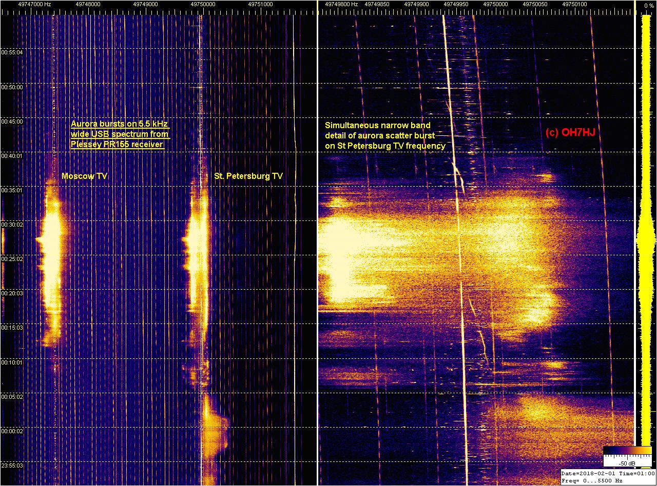
How to tell the approximate direction of a natural high sky radio scatter? Here is how I estimate the general direction of strong 6m TV band scatters with single aerial and receiver method of known TV transmitters used as radio scatter beacons. [/b]

It is known that the baseline forward scatter effect greatly increases scatter intensity when the scattering target is close to the Rx - Tx baseline. This applies both for natural and artificial radio scatter targets. When scattering target is farther away from Rx - Tx baseline the signal strength of scatter decreases.

With very powerful TV Tx’s as beacons, radio scatters are visible from far away from baseline high sky targets as off-baseline backscatters. With small power TV Tx’s as beacons, only targets close to Rx - Tx baseline create observable scatters because the baseline forward scatter effect boosts their signal intensity.

Direction Estimate of Radio Scatters by TV Tx’s

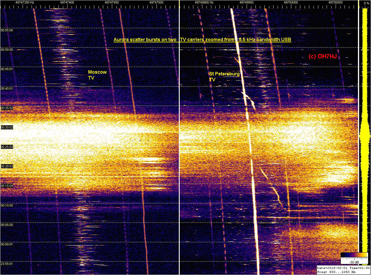
On the R1 (OIRT1) TV carrier freq of 49750 kHz there are many TV Tx’s a few kHz apart from each other. Looking at the attached R1 TV channel spectrum strips, one can see that some natural scatters appear simultaneously on some of the known TV Tx carrier freqs marked at the scale above the screenshots.

By the directions marked to the TV Tx’s on the scale, one can make a rough estimate about the general direction of each scatter by which Tx freqs they appear on simultaneously.

I have marked and joined with lines some examples of the simultaneous natural high sky electric scatters on the spectrums. There are lots of natural scatter occurring every few seconds on this R1 TV channel so it is rather easy to spot them with modest equipment.

High sky electric discharge scatters seem occur at about similar altitude as Es scatter and be related to them, so their visibility range is comparable to 50 MHz Es ranges. So, Central Europe is not away from R1 TV electroscatter observing range. :wink:

73, T: - Juha -


2017-11-28-1252 HDSDR RTL IF FT100D OIRT1 Y12H 100 - Medium fast strip - Simultaneous natural EDS bursts (c) OH7HJ.JPG

With aerials in low interference station location a long time observer could spot meteor scatter head echo scatters triggering some of these electric discharge scatters. For example, Esko OH2AYP has managed to spot some nice narrow doppler meteor scatter (MS) dopplers preceding spread spectrum electric discharge scatters (EDS).

Attached are a few pics of Esko’s MS dopplers on two TV Tx freqs. The upper one is St. Petersburg TV and the lower one is Moscow TV, both on 6m band R1 TV channel. Freq scale is about the width of receiver SSB filter. Much wider doppler shift indicating very high velocity together with short duration of the doppler distinguishes meteor scatter dopplers from usual aircraft scatter (AS) dopplers.

The actual meteor trail scatter is visible as narrow doppler (head echo). In some of his pics, the meteor trail appears to trigger a typical irregular spread spectrum electric discharge scatter following the actual narrow meteor doppler. In another pics, there is no electric dischage scatter following the meteor doppler. So a meteor trail may usually initiate a natural electric discharge that shows as a spread spectrum scatter.

The electric discharge scatter is usually much stronger and longer lasting than the preceding meteor scatter trace that appears to trigger it. However, usually there is no evidence of any meteor trail doppler preceding the ED scatter. So it appears that meteor trail may initiate a natural atmospheric electricity discharge but not always. There are a lot more natural ED scatters than meteor dopplers so most high sky natural electric discharges seem to be initiated spontaneously.

Spotting MS from among ED scatters - 2: viewtopic.php?f=21&t=295&p=2497#p2497
Spotting MS from among ED scatters - 3: viewtopic.php?f=21&t=295&p=2498#p2498

73, - Juha
mf20160708103220_20160708103445_crop - Meteor head echo doppler - Rx at Vesanto - Moscow and St Petersburg TV - Freq resolution abt 10 Hz per pixel - Time 10 px per s - OH2AYP.jpg
mf20160712093101_20160712093333_crop - Two meteor head echo dopplers - Rx at Vesanto - Moscow and St Petersburg TV - Freq resolution abt 10 Hz per pixel - Time 10 px per s - OH2AYP.jpg
mf20160712154010_20160712154243_crop - Meteor head echo dopplers - Rx at Vesanto - Moscow and St Petersburg TV - Freq resolution abt 10 Hz per pixel - Time 10 px per s - OH2AYP.jpg

A sequence of strong and wide EDS flare or burst natural high altitude scatter occurring on the R1 TV channel. The strength of this flare scatter was strongest on the NEE pointing yagi of my aerials. So I guess this scatter originated from somewhere in North direction. The scatter starts and strengthens quickly and fades gradually in a few minutes which is usual to wide strong flares like this. Momentary spectrum of the flare at top appears to be a symmetric one of an analog TV, with weak center carrier.

The TV Tx of this scatter is unknown and its center frequency of abt 49749.5 kHz is unlisted. Might be some of the Kola dirstrict local TV Tx’s. I added to one of the pics the ‘scale’ of known TV Tx’s. Such wide flares as this occur irregularly from every tens of minutes to every few hours. Sometimes their rate increases before high sky electric activity periods like before aurora borealis spread noise spectrum discharge scatters begin.

These are slow moving monitor strip pics so I can not tell if there were any MS doppler head echo triggering the burst. By shape it is a usual wide TV Tx scatter flare that appears be caused by ionizing high altitude electric discharge. Compared to the Segezha Nadvoitsy TV visible on the same spectrum with sharp side band lines, the wide natural scatter burst has its side band lines merged together. This is a distinctive spread spectrum effect of high sky electric discharge scatters (EDS).

Time stamps at left are UTC + 2 hours. Aerial is a 6-el yagi pointing abt direction 030. Receiver is a RTL dongle working with HDSDR software. The Segezha Nadvoitsy TX is constantly visible with sidebands strong in freezing subzero during night and fading when temperature is rising above 0 C in daytime. An earlier less intense wide EDS flare visible on the strip has occurred less than an hour earlier.

Strong 6m TV High Sky Scatter - Part 2: viewtopic.php?f=21&t=295&p=2421#p2421

Soon after I had reported about the wide strong natural scatter there appeared an aurora scatter. The aurora was a short burst lasting for a couple hours only. After aurora had stepwise faded out, there appeared one more wide natural burst following it. After this there were no similar strong natural wide bursts for hours.

It might be possible that these wide strong scatters were once again related to high sky electrostatic discharge activity, like accumulating high voltage ionospheric charges that seem to be related to birth of aurora borealis (Northern lights), too?

Solar wind is known to constantly bring positive static high voltage charges to the upper ionosphere. Electrostatic explanation of Northern lights discharge suggests that aurora borealis is a high voltage discharge between polar rims of ionosphere opening (aurora belt) and charged solar wind environment. This model explains easily the curtain shapes of visible aurora discharges in the sky, as well as aurora discharge movements along with night time movement of polar opening of ionospheric layers.

Strong 6m TV High Sky Scatter - Part 1: Aircraft Scatter - Lentokoneheijastus ja sen doppleri.

Oheiskuvana on leveä tutkanauha aurorapurkauksesta, sekä sitä ennen ja sen jälkeen esiintyneistä leveistä ja voimakkaista korkean taivaan luonnollisista sähkönpurkausheijastuksista (EDS). Nauhan alalaidassa näkyvät edellisen aamuyön aurorapurkausheijastusten pätkät.

Näiden vahvojen sähkönpurkausten luonnetta ei vielä tunneta. Niillä on kuitenkin luonnollisten korkean taivaan sähkönpurkausten moduloimille radioheijastuksille luonteenomainen hajaspektri. Arvauksen mukaan ne saattavat liittyä ylempiin ionosfäärisalamiin.

Revontulipurkausten radioheijastukset (Aurora Scatter) sekä voimakkaat leveät sähkönpurkausheijastukset (Wide EDS) on ympyröity spektrinauhalle. Aikaisempia havaintoraportteja samankaltaisista voimakkaista sähkönpurkausheijastuksista ennen ja jälkeen revontulipurkausten:

Strong 6m TV High Sky Scatter - Part 1 - Kerhon kaluston lainausvihko
Strong 6m TV High Sky Scatter - Part 2 - Aircraft Scatter - Lentokoneheijastus ja sen doppleri.

Vastaanottimena havainnossa on RTL-SDR, softana HDSDR, ja antennina 6-el 50 MHz jagi suunnattuna pohjoiseen.

T: - Juha

Lisää arvoituksellisia leveitä ja voimakkaita korkean taivaan sähkönpurkausheijastuksia tutkanauhoilla.

Näköhavaintoja kaivattaisiin ilmiöiden tunnistamiseksi, mutta niitä on tunnetusti vaikeaa saada täältä pilvien alta…

Nämä näkyivät eilen pohjoisen suuntaa havainnoivalla antennilla. Samankaltaisia näkyy satunnaisesti myös idän suunnalla. Aikaleimat ovat Suomen aikaa.

Strong 6m TV High Sky Scatters:

Part 1 - Kerhon kaluston lainausvihko
Part 2 - Aircraft Scatter - Lentokoneheijastus ja sen doppleri.
Part 3 - viewtopic.php?f=21&t=295&start=170#p2426
Part 4 - viewtopic.php?f=21&t=295&start=170#p2427

Kuva: 2017-12-19-2034 FT - OIRT1 HDSDR SL Y6E 360 Segezha - Three wide EDS bursts © OH7HJ.JPG

T: - Juha

Leveänä nauhana tutkakuvassa näkyvä voimakas sähkönpurkausheijastus osui yksiin tutkassa pystysuuntaisina ‘lieskoina’ näkyvän alkavan revontulipurkauksen tilapäisen taukoamisen kanssa.

Leveän tutkanauhan kuvaa: 2017-12-30-2025 FT - OIRT1 HDSDR Y6H 360 Segezha TV - Wide EDS during pause of aurora discharge © OH7HJ

T: - Juha

Uudenvuodenpäivän iltapäiväinen revontulipurkaus oli varsin voimakas, ja sekaan leimahteli leveitä voimakkaita yläsalamapurkausten radiokaikuja. Tavallisesti aurorapurkausta ja tällaisia voimakkaista leveitä yläsalamaheijastuksia ei näy yhtaikaa, vaan leveät sähkönpurkausheijastukset esiintyvät ennen revontulipurkausta, tai sen jälkeen.

Arvaan purkausten yhtaikaisuuden ja voimakkuuden saattavan merkitä, että aurinkotuulen puhuri on tuonut aimo annoksen taivassähköä. Nyt aurinkotuulen tuomaa sähkövarausta lienee tullut riittävästi purkautumaan samanaikaisesti sekä revontulina, että yläsalamoina…?

Leveät korkean taivaan sähkönpurkausheijastukset näyttävät liittyvän joskus revontulten alkamiseen tai päättymiseen. Niin kävi nytkin. Aurorapurkaus taukosi klo 16.45, minkä jälkeen leimahti revontulitutkan nauhalle yksi voimakas leveä sähkönpurkauskaiku lisää. Revontulikaiut näkyvät tällä leveällä nauhalla pystysuuntaisina ‘lieskoina’. Leveät sähkönpurkausheijastukset puolestaan näkyvät vaakasuuntaisina, yläreunaltaan sahalaitaisina juovina.

Tutkanauhan alemman ikkunan radiospektrinauhan liikesuunta on ylhäältä alaspäin. Aikaleimat nauhan vasemmassa reunassa ovat Suomen aikaa. Päiväys on kuvien tiedostonimessä. Taajuudet näkyvät kilohertseinä taajuusasteikolla spektri-ikkunoiden välissä.

T: - Juha


A simple multi-frequency reception experiment on part of 49750 kHz OIRT1 TV channel spectrum with traditional analog HF communications receiver Plessey PR155 which has filter for 6 kHz wide USB. This is a moderate increase of rx bandwidth which allows receiving two instead of previous one TV tx carrier frequencies at the same time with single aerial and receiver. Here the two freqs are Moscow TV and St Petersburg TV carriers about 3 kHz apart from each other.

First screenshot shows an aurora discharge burst at left on 5.5 kHz wide bandwidth Spectrum Lab display from part of the R1 TV channel spectrum. Moscow TV and St Petersburg at wide spectrum strip left and St Petersburg zoomed as detail at right SL strip. Both were received simultaneously with same receiver and aerial. Scale at top of each strip shows frequency as Hz.

SL2 Y6U PR155 OIRT1 5.5 kHz wide spectrum - Moscow - St Petersburg © OH7HJ - 2018-02-01-0100 - Aurora burst.jpg

Second screenshots shows at left strip Moscow TV and at right strip St Petersburg TV carrier aurora bursts zoomed still wider with simultaneously plotting another example of Spectrum Lab reading the same PR155 receiver through tiny USB audio stick. Sorry for heavy freq drift of the veteran rx and its converter. Neither are near modern stability standards.

The two Spectrum Labs reading receiver sound through an USB audio dongle consume minimal amount of computer power. The same computer reads and plots at the same time sound inputs from two more 50 MHz ham receivers with still one SL example, plus listens to aircraft ADS-B signals with a RTL1090 SDR to plot them on Planeplotter map: maanpuolustus.net/pages/tutka/

This makes a single computer monitor, analyze and save simultaneously 6 spectrum strips and 5 frequencies. Processing power of this pre-Millennium era Fujitsu Scenic desktop running multi analog rx’s and SL windows is about similar to modern Raspberry Pi. Multi frequency and multi spectrum analysis from wide band audio sound feed from single receiver and aerial appears feasible.

SL3 Y6U PR155 OIRT1 - Zoomed from 5.5 kHz wide spectrum - Moscow and St Petersburg © OH7HJ - 2018-02-01-0100 - Aurora burst.jpg

On third screenshot an example of how switching Plessey receiver filters affect monitored bandwidth visible on Spectrum Lab strips.

Filter responses are rather bumpy which is normal for analog receivers like PR155. Modern SDR’s produce nice flat and straight frequency spectrums from their digital filters. I hope that I can get some of the new wide audio SDR’s work in my computers to continue multi frequency experiments with.

2018-02-01-1223 SL3 Y6U PR155 OIRT1 - 5.5 kHz wide USB spectrum - Comparing bandwidths of 0.3 and 3 and 6 kHz rx USB filters © OH7HJ.jpg

Regards,

Continued from previous message.

Equipment pics: A 50 MHz converter equipped Plessey PR155 HF receiver dating from early 1970’s was used with this experiment because it was my only rx that could listen to rather wide audio USB with its AM filter of about 6 kHz bandwidth and adjustable beat.

Only digitizing device between the PR155 receiver and computer was an inexpensive USB sound stick.

Regards,

A regular repeating flight pattern doppler appeared on St Petersburg TV and Segezha Nadvoitsy TV strips. It appeared to belong to an ATR plane of flight FIN51G circling around. Doppler vanished as the plane apparently descended below Tx radar horizon for landing to EFJO.

FR24 map view plotted some irregularities to its track. Reason is that this ATR carries only the ‘old style’ mode A/C transponder which does not transmit GPS location of the aircraft.

The FR24 receiver network uses for non-ADS-B mode-S transponder flights MLAT means of locating by its signal time difference of arrival (TDOA). MLAT is less accurate than ADS-B and causes deviations of plane location here visible as aircraft fake sudden jumps southeast on the FR24 playback map. Dopplers tell its real movements.

Online archive spectrum strips of the circling flight doppler:

maanpuolustus.net/muut/tutka/ku … /11_30.jpg
maanpuolustus.net/muut/tutka/ku … /12_00.jpg

An experiment with a multi frequency receiving configuration aboard a car to see what kind dopplers one gets while moving on road. Receiver was a common RTL-SDR with newest version of software SDR Console V3 which Jesse OH2BIX kindly instructed me how to configure to provide R1 TV wide band voice containing all TV transmitter carriers of doppler interest, thank you!

The wide band ‘radar sound’ from SDR-V3 was further streamed through VB-Cable mixer software to 10 separately configured Spectrum Lab windows. From this ‘doppler radar voice’ were separated and plotted narrow band detail strips of eight R1 TV channel transmitters plus a wide band spectrum of entire 22 kHz wide central R1 TV spectrum. This configuration allows monitoring, measuring and saving simultaneously all carriers of the OIRT1 band with a single receiver and single aerial using easily available free software.

Receiving aerial was a horizontal omnidirectional V-dipole built of carbon fiber rods and of glass fiber broom shaft attached to wooden mounting piece held on car roof by magnets. A Thinkpad T61 laptop was running the receiving software with RTL receiver attached to its USB port.

Links:

R1 TV channel wide band ‘doppler radar voice’ online demo: maanpuolustus.net/pages/tutka/

SDR Console V3 receiving software: sdr-radio.com/Software/Downloads

VB-CABLE Virtual Audio Device: vb-audio.com/Cable/

Broadband twin lead match for a 6m band dipole: Rigien ja antennien dB-mittauksia

A combined Spectrum Lab display of multi freq receiving experiment detail strips of TV carriers from receiver in a moving car. Some of the carrier freq drift visible on St Petersburg and Segezha TV strips is from RTL receiver drift but much of it is caused by moving car velocity doppler shift. Joutseno TV and FM broadcast mast strong RF field appeared to deafen the RTL receiver stick at around 11.20 to 11.30 oc on this six TV frequencies set of spectrum detail strips causing black sections on them.

The first part of mobile measuring drive was to general direction of south and southwest. As the mobile receiver was driving farther away from Segezha Nadvoitsy TV Tx its signal faded and tended to shift a little down by doppler effect of car velocity. At the same time the mobile Rx was approaching nearer St. Petersburg TV Tx in south which caused its signal level to increase and shift a little upwards by doppler effect. However, when the ‘twists’ of both carriers are to the same direction it is probably caused by RTL Rx freq drift. Those twists that are to opposite directions between the two TV carriers are caused by car velocity doppler shift of reception.

The SDR V3 receiving software was set to stream a 22 kHz wide voice of two wide filter USB VFO’s divided to both stereo channels of a single audio stream channel. This stereo ‘radar voice’ was streamed through VB-Cable to ten independently analyzing and doppler separating Spectrum Lab windows. TV transmitters and their carrier frequencies are on the list above detail strips and there is a freq scale in Hz above each detail strip. Bandwidths of TV carrier detail strips vary between 100 … 200 Hz. Time stamps are Finnish local.

A wide spectrum R1 TV channel slow strip from returning by a route a little different to arrival. In the beginning unstable urban city noise governs the radio spectrum background. Then there are again the already familiar black sections of deafened receiver at the same places as during arrival trip. Probable reason for one of the receiver blackouts is the BC-FM broadcast tower strong RF field.

Background interferences gradually settle down when driving through less populated environment, with an exception of the car onboard a ferry. The open lakeside together with steel deck of the ferry appears raise background noise and interference levels.

Aircraft scatter dopplers are visible as slant lines on the St. Petersburg TV carrier at about 17:12, 18:08, 18:12, 18:23 and 19:08. Parallel to carrier sets of vertical lines are TV 50 Hz side bands. Short sideways spreading marks on many TV carriers are natural scatters like EDS of high sky lightnings. Continuous wandering unstable interferences are coming possibly from car electronics. Time stamps are Finnish local.

The spectrum strip attached is combined from two separately analyzing Spectrum Lab windows. First window at left plots the lower R1 TV channel spectrum through left audio channel and the right SL window plots upper spectrum from right audio channel. Return track on map was created online from an APRSdroid software installed to a GPS equipped android mobile phone.

Examples of meteor scatter ‘head echo’ dopplers captured by Esko OH2AUP from live ‘radar voice’ of OH7HJ R1 TV channel online streaming receiver. The receiving setup of this experiment is a 4-element almost omnidirectional 50 MHz horizontal dipole array with an RTL receiver and SDR Console V3 software streaming a 22 kHz wide TV channel spectrum as two wide band USB sound streams divided to both stereo channels of single MP3 online voice audio channel.

The fast sweep multi TV carrier spectrums by Esko show meteor scatter (MS) narrow dopplers scattered from the very fast velocity of meteors striking down to upper atmosphere and creating ionized trail which scatters TV carriers of 6m band R1 TV channel. Some of the MS doppler pics show meteor dopplers simultaneously on two TV carrier frequencies.

These actual MS head echo dopplers are rather weak which makes it difficult to capture them on low power radio beacons. With high power beacons like these TV carriers meteor dopplers are much easier to spot. Their usual spread spectrum ‘tails’ following meteor head echo dopplers are strong and long lasting which makes the electric discharge tail scatters very easy to capture compared to head echo dopplers of actual meteors.

However, these natural ionospheric electrostatic discharges alone are not necessarily evidence of actual meteor hits. Also, not all meteor head echo dopplers trigger these spread spectrum electric discharge tails. Natural high sky electric discharge scatters (EDS) occur all the time and vast majority of them appear lack any evidence of meteor head echo dopplers. This suggests that most of these longer than MS head echo doppler lasting natural ionospheric discharges are ignited spontaneously, possibly by voltage of naturally accumulating atmospheric electrostatic charge exceeding threshold level of ionospheric electricity discharge.

Meteor Scatter Spectrum Strips

Esko tells that the attached pics are copied with a single audio channel spectrum software so the lower and upper R1 channel TV carrirers show on the same MS strips. Fortunately they overlap so they can be spotted.

These strips do not have frequency or time scales but his fast registered strips have a sweep of 43.066 Hz per pixel and zero beat is the low edge os the strips representing freqs 49739 and 49755 kHz. Middle registered strips are 4 times slower.

For example, the highest strong carrier of this middle registered MS strip is St Petersburg TV and below the center one with many EDS is Moscow TV. Near low edge is Syktyvkar TV: midle20180227060100_20180227060739 - 7000 - 12000 Hz - MS doppler up left - MS head echo dopplers from online live OH7HJ radar stream captured by OH2AUP.gif

Online Radar Voice

The online multi-static radar voice is freely available for online listeners of AS dopplers as well Es and Aurora scatter or MS spotters. Lower R1 band is on left stereo cahnnel and its audio zero beat is 49739 kHz. Higher TV band starts at 49755 kHz zero beat and it is on right stereo channel.

The sound can be picked up from standard web browser through a virtual audio cable software like VB-Audio Cable by setting it as ‘Default Audio Device’ on windows playback devices menu. Then the virtual cable is selected as input audio device for the sound spectrum analyzer software you prefer. Set it listen to left stereo channel for low R1 TV band carriers and to right stereo channel for high band carriers.

These streams are rather easy to spot by anyone familiar with audio spectrum analyzer software like Spectrum Lab. Please ask me for ready Spectrum Lab INI or USR setup files for either wide band R1 carriers or for detail strips of each TV carrier.

Links:

‘Radar voice’ is available online at MPnet multi-static radar demo page: maanpuolustus.net/pages/tutka/
DL4YHF’s Audio Spectrum Analyzer Spectrum Lab download: qsl.net/dl4yhf/spectra1.html

Spotting MS from among ED scatters - 1: Aircraft Scatter - Lentokoneheijastus ja sen doppleri.
Spotting MS from among ED scatters - 3: viewtopic.php?f=21&t=295&p=2498#p2498

Regards,

More of Esko’s MS head echo dopplers captured from the live audio radar stream are attached below.

For listeners of the online ‘radar voice’ of R1 TV channel carriers here are appx. audio frequencies for some easily visible TV transmitters from the stereo audio stream to help with configuring spectrum analyzer software for remote monitoring with one’s home computer:

URL of ‘radar voice’ stream: maanpuolustus.net/pages/tutka/

Left Stereo Channel

  • Arkhangelsk and Cherepovets TV 590 Hz
  • Kirov TV 1890 Hz
  • Sekezha Nadvoitsy TV side band 3170 Hz
  • Syktyvkar TV 7100 Hz
  • Moscow TV 8420 Hz
  • St. Petersburg TV 10985 Hz
  • Segezha Nadvoitsy TV 18825 Hz

Right Stereo Channel

  • Segezha Nadvoitsy TV 2825 Hz
  • Nyandoma TV 5400 Hz

Please notice that there is some time delay with the online internet audio transfer. I am not skilled enough with sound streaming software to make it transfer time codes. Advice with exact streaming software is appreciated!

True frequencies for some TV transmitters

  • Arkhangelsk TV, LP04GN, freq 49739.583 kHz.

  • Cherepovets TV, KO89WD, freq 49739.586 kHz.

  • Moscow TV, KO85TT, freq 49747.413 kHz.

  • St. Petersburg TV, KO59DX, 49749.975 kHz.

  • Kotkozero TV, KP61OG, freq 49749.998 kHz.

  • Malozhma TV, KP94DD 49755.187 kHz.

  • Suoyarvi TV, KP62EC, freq 49750.016 kHz.

  • Ruskeala TV, KP51HW, freq 49757.806 kHz

  • Segezha Nadvoitsy TV, KP73CW, 49757.818 kHz.

  • Nyandoma TV, LP01CQ, 49760.401 kHz.

  • Juha
    fast20180227060254_20180227060431_crop - MS doppler above two TV freqs - MS head echo dopplers from online live OH7HJ radar stream captured by OH2AUP.gif
    fast20180227074031_20180227074210_crop - Two MS dopplers - Second on two freqs - MS head echo dopplers from online live OH7HJ radar stream captured by OH2AUP.gif