Aircraft Scatter - Lentokoneheijastus ja sen doppleri.

Natural common high sky spread spectrum radio scatters of faraway TV transmissions sometimes create curious patterns on the spectrum strips. With the Spectrum Lab radio direction finding (RDF) option, we can now approximately tell at which direction each scatter occurs.

Here are curved scatters of TV transmission side bands that resemble hooks. Their peculiar dividing form may be caused by natural ionospheric electrostatic discharges with streamers extending to two or more directions, each streamer creating a branch to its spectrum by doppler effect. These natural scatters could be called ‘doppler forks’ or ‘doppler hooks’ by their appearance.

High Sky ‘Doppler Hook’ Appearing

Here is how one of these spectrum spreading doppler fork curiosities look like on a RDF spectrum with each color indicating SL direction of the signals on the spectrum. At left the emerging scatter is seen on a fast spectrum strip. At right a 10 minute strip is plotting it, and at center it has been captured by a one hour spectrum strip. This doppler hook is a rather long lived one and it has clear spread spectrum branches.

The third pic shows a detail of this doppler hook discharge scatter on a 10 minute spectrum strip. At left is circled the direction of abt 156 degrees that the SL RDF function suggests this scatter is propagating from. Narrow curves are aircraft dopplers changing color while the flight advances. Upright lines are TV carriers and side bands. Very wide ‘noise clouds’ that resemble brief aurora scatters are possibly very high altitude ED scatters.

Rather wide spread specrum and long life time of the scatter like this is supposed to be created by electric discharge scatters (EDS) in high altitudes while ones on lower altitudes seem to be those of shorter life time and they have less wide spread spectrums.

6m 4+4-el Crossed RDF Loop - oh7ab.fi/foorumi/viewtopic.p … 2613#p2598

An example how three aircraft dopplers flying the same route look like on Spectrum Lab Radio Direction Finding (RDF) strip with a crossed 4-el loop array aerial XQ4H on Segezha TV carrier frequency. Their route is close to parallel to Rx - Tx baseline so their dopplers are plotted almost parallel to to the TV carrier for a while.

First pic shows the three dopplers joining TV carrier frequency after the planes pass by Segezha Nadvoitsy TV Tx. Map view is Planefinder.net.

Second screenshots shows their dopplers extracting from the TV carrier as they are bypassing my Rx location. Dividing ‘fork doppler’ is caused by a strong aircraft doppler signal strength close to Rx making intereference ‘mirrors’ and ‘twins’.

Third image illustrates several simultaneous dopplers of planes plotted on the RDF strip. Colors indicate RDF directions calculated by Spectrum Lab from aerial phase shifts.

More example SL RDF dopplers of a rush of aircraft. Setup is same as with previous message. Segezha TV carrier is close to zero Hz marker of the Spectrum Lab RDF strip.

Pic 1: Among usual aircraft scatter dopplers there is a smaller sharp ‘doppler hook’ near the center of the SL strip. This may be created by a natural high sky dividing electric discharge scatter (EDS).

Pic 2: The TV carrier at about -7.5 Hz position of the spectrum strip is Ruskeala TV carrier. Here it has a typical steep rather short aircraft doppler of a plane crossing the Rx-Tx baseline. At the spot marked with cross cursor Spectrum Lab has calculated its RDF direction to be 139.3 degrees from Rx. Ruskeala TV Tx is at abt 140 degrees from my Rx so the RDF calibration seems to be rather good.

Pic 3: Extracting doppler of an aircraft with mirror ‘twins’ caused by strong doppler scatter signal interference. SL RDF suggests 139.4 degrees as direction of Ruskeala TV Tx at mouse cursor point. RDF directions of faraway TV Tx’s vary possibly because multipath effect of surface wave propagation. Above horizon signal source like aircraft doppler RDF directions usually keep rather accurate probably because sky wave propagates directly without need to seek alternative paths like surface wave usually does.

Link to RDF aerial 6m 4+4-el Crossed RDF Loop XQ4H: oh7ab.fi/foorumi/viewtopic.php?f … =200#p2598

Radio Direction Finding (RDF) by two or more aerials allows also many other applications than just direction finding. In principle, any two separate receiving aerials used with a coherent two or multi channel receiver allow assorting signals by their phase shifts. Here are examples of experiments separating desired signals from unwanted noise and interference.

Bare noisy digimode signals are at left with Spectrum Lab RDF screenshots. At right desired signals have been separated by their RDF ‘color’ which indicates signal phase shift. Because there are yet no directional filter software available, I imitated directional filter effect with Picture Publisher software color picking tool.

The qraphical editing tool of this demonstration is of course too ‘hard’ making abrupt signal outlines but the pics should give a rough idea about how direction of wave arrival could be used for selecting desired radio signals. Proper practical signal processing software introducing directional filter would work ‘softer’.

Example signals were spotted and plotted from 160 m band at 1843 kHz LSB with a coherent pair of FT100D receivers. Aerial was the same 6m band XQ4H crossed loop used for my 50 MHz experiments. Despite that the aerial is in this 160 m case built for ‘wrong’ band the crossed loop appears to works on other bands, too, providing necessary phase shift for HF directional filtering effect demonstration.

Regards, - Juha


The experimental multi-static radar listening to 6m band TV carriers streams almost real time USB audio which is quite good for monitoring meteors scatters and their head echo dopplers (MS HE). Here are instructions to set up your Windows home PC to receive and plot this radar sound stream with MS head and tail echoes on your own computer screen.

  1. Load and install Spectrum Lab software by Wolf DL4MH. qsl.net/dl4yhf/spectra1.html

  2. Open two windows of Spectrum Lab.

  3. Load the attached archive file “Remote MS monitoring setup files for Spectrum Lab.rar” and extract them to some folder. This archive contains two Spectrum Lab USR setup files for MS plotting from the remote USB sound stream.

  4. Then load each of these setup files to one of the Spectrum Lab windows from: File > Load Settings from > browse for these two files. “SL1 MS 40mS-line PK-M 49739-49752.USR” configures Spectrum Lab window for low R1 TV band and “SL2 MS 40mS-line PK-M 49755-49762.USR” for high R1 TV band MS plotting.

  5. Download and install some virtual audio cable software you prefer. This software usually installs and works well: vb-audio.com/Cable/

  6. Set this virtual audio cable as Windows default playback device. See the attached screenshot.

  7. Set both Spectrum Lab audio input devices for the virtual audio cable: Options > Audio Settings > Input Device / Stream / Driver > Cable Output (VB Audio). See the illustration attached.

  8. Set your web browser for maanpuolustus.net/pages/tutka/ . Turn its audio volume to maximum. Now the USB sound stream should be flowing to the virtual audio cable. Remark! If your web browser has no volume adjust control visible on the page, try another browser! Internet Explorer usually has a volume control. See the example screenshot below.

Finally apply Spectrum Lab settings. If you got it correct the Spectrum Lab windows should start plotting R1 channel TV from the online streaming radar sound. Then streatch the Spectrum Lab windows proper for you to view them.

Scale with usual OIRT1 channel TV transmitters is on notepad windows above the Spectrum Lab streams that I have put on this thread. Attached are text files of them as archive “Usual R1 TV band transmitters for editing a text file frequency scale © OH7HJ.rar”.

Regards, - Juha OH7HJ
Usual R1 TV band transmitters for editing a text file frequency scale © OH7HJ.rar (785 Bytes)
Remote MS monitoring setup files for Spectrum Lab.rar (19.9 KB)

For automatic capturing of meteor scatter head echoes (MS HE), Timo OH7HMS kindly suggested using a MS capturing script with Spectrum Lab. Knowing that MS HE’s are rather difficult to automatically capture by their signal levels because they are much weaker and less frequent than the common high sky spread spectrum electric discharge scatters (EDS), I was dubious about it. However, there were MS capturing scripts accompanied with Spectrum Lab so I tried one created by Simon Dawes.

Right away there appeared a way to use the frequency range setting of the script to help identify long MS head echoes from among usual strong electric scatters. Strongest MS’s usually draw their head echo doppler lines up to hundreds of Hz above the beacon tx freq. For them, I set the script to watch only those scatters 100 Hz or higher above the 6m powerful Tx of Moscow TV at 49747.41 kHz that gives nice MS HE’s from wide range of sky.

First time trying, Simon’s MS script captured overnight 254 screenshots, of which 101 were left after I removed short HE’s and EDS bursts and missed ones. A lot of 254 screenshots captured by his MS script is a lot easier to check through than thousands of automatic screenshots saved every half minute or so. It means, that Simon’s script works!

Here are some samples of MS HE’s selected from among those automatically captured and labeled by the script. Frequency scale is up and time scale at left with SL time stamps as UTC+2h local and script time stamps as UTC. Spectum strip speed is 40 ms/line. The aerial used was the same 2x4-el crossed horizontal loop XQ4H and receivers the coherent pair of FT100D’s as with my earlier 6m band RDF experiments. Signals on the spectrum screenshots are colored by Spectrum Lab’s radio direction finding (RDF) function by their direction of arrival.

Regards, - Juha OH7HJ

Please click images below to open them.


Color changing MS HE dopplers:

Spectrum Lab RDF function has made colors of these meteor scatter head echo (MS HE) dopplers change by their direction of arrival.

By my first guess, those MS HE dopplers that change their RDF color are likely to be so close to receiving station (Rx) that while they travel on high sky they make a wide enough angle seen from Rx to change their RDF color on spectrum strip.

Here are some examples of these meteor scatter dopplers that change their RDF color while drawing their ionized tails on sky high above us. A reference SL RDF color circle is at right down corner of each MS HE screenhot. Receiving and capturing setup is the same as with previous report.

Regards, - Juha OH7HJ

Please click screenshots below to expand them.


[b]Heavenly Meteor Blues:

Those meteor hits that occur near the Rx-Tx baseline are the strongest because of the baseline forward scatter (BFS) effect. The BFS effect increases scatter signal level about 20 dB or so compared to off-baseline scatters. That is why usually most MS HE dopplers plotted appear to come from the direction of transmitting station (Tx), which in this experiment is the Moscow TV on OIRT1 channel at southeast from receiving station (Rx). [/b]

However, because this 6m band Moscow TV Tx has a very high ERP power it brings visible also some meteor scatters from away from the Rx-Tx baseline. These are colored by the SL RDF function by their direction. Because Rx-Tx baseline to Moscow points at southeast from my Rx, most usual RDF colors for MS are yellow, green and cyan which represent approximate Moscow TV baseline direction on the Spectrum Lab RDF color circle visible on the low right corner of screenshots.

Most usual ones of the rather weak off-baseline meteor scatters visible on these SL strips are red scatters which represent northeast and blue scatters from south direction of the SL RDF color circle. Here are attached some of those evidently from south of my Rx propagating off-baseline blue or RDF color changing partly blue meteor scatter HE dopplers.

Regards, - Juha OH7HJ

Please click screenshots below to expand them.


[b]‘High Flyers’:

Some MS HE dopplers plot interrupted lines on SL spectum strips even if they provide clear strong scatter signal. Because almost all of these dopplers have high dopplers shifts I am using for them a short name of ‘high flyers’. These high dopplers are not very usual but there appear a few of them daily on these 6m band TV Tx carriers. [/b]

The cause of this kind high interrupted doppler may be either meteor trajectory or bistatic scatter geometry or quick velocity or charge loss or meteor falling apart, to guess a few.

As an example of trajectiories, a meteor ‘scratching’ upper atmosphere and escaping again might draw this kind interrupted high doppler. Quick velocity loss might make them decelerate below ionizing speed. Lightweight meteors naturally decelerate quicker than heavy ones.

If ionizing is agitated by meteor electric charge then fast charge loss would cause same. If a meteor is suddenly fragmentized by shock of hitting atmosphere it of course is decelerated quickly, too.

Experiment setup is the same as with my previous meteor RDF reports.

Regards, - Juha OH7HJ

Click screenshots below to expand them.


Jussin OH7TE ystävällisesti Ilkan OH5IY softalla laskemat joulukuun 2018 geminidien meteorisateen saapumissuunnat vuorokaudenajoittain.

  1. päivä joulukuuta klo 23 UTC eteenpäin on sateen maksimi, ja radiantti silloin melko etelässä. Näistä näkyy graafisesti, kuinka korkealla meteorisateen säteilypiste on.

Laskettu lokaattorille KP30HV. Kellonajat näkyvät tiedostonimissä ja ovat UTC. Osa 1.

T: - Juha
GEMINIDS_2018 - 00 UTC.jpg
GEMINIDS_2018 - 09 UTC.jpg
GEMINIDS_2018 - 16 UTC.jpg

Jatkoa edelliseen, kuvat illalle klo 18 ja 23 UTC.

T: - Juha
GEMINIDS_2018 - 18 UTC.jpg
GEMINIDS_2018 - 23 UTC.jpg

[b]Havainto: Auroraheijastuksen polarisaatio vaihtui vaakasuuntaisesta pystysuuntaiseksi.

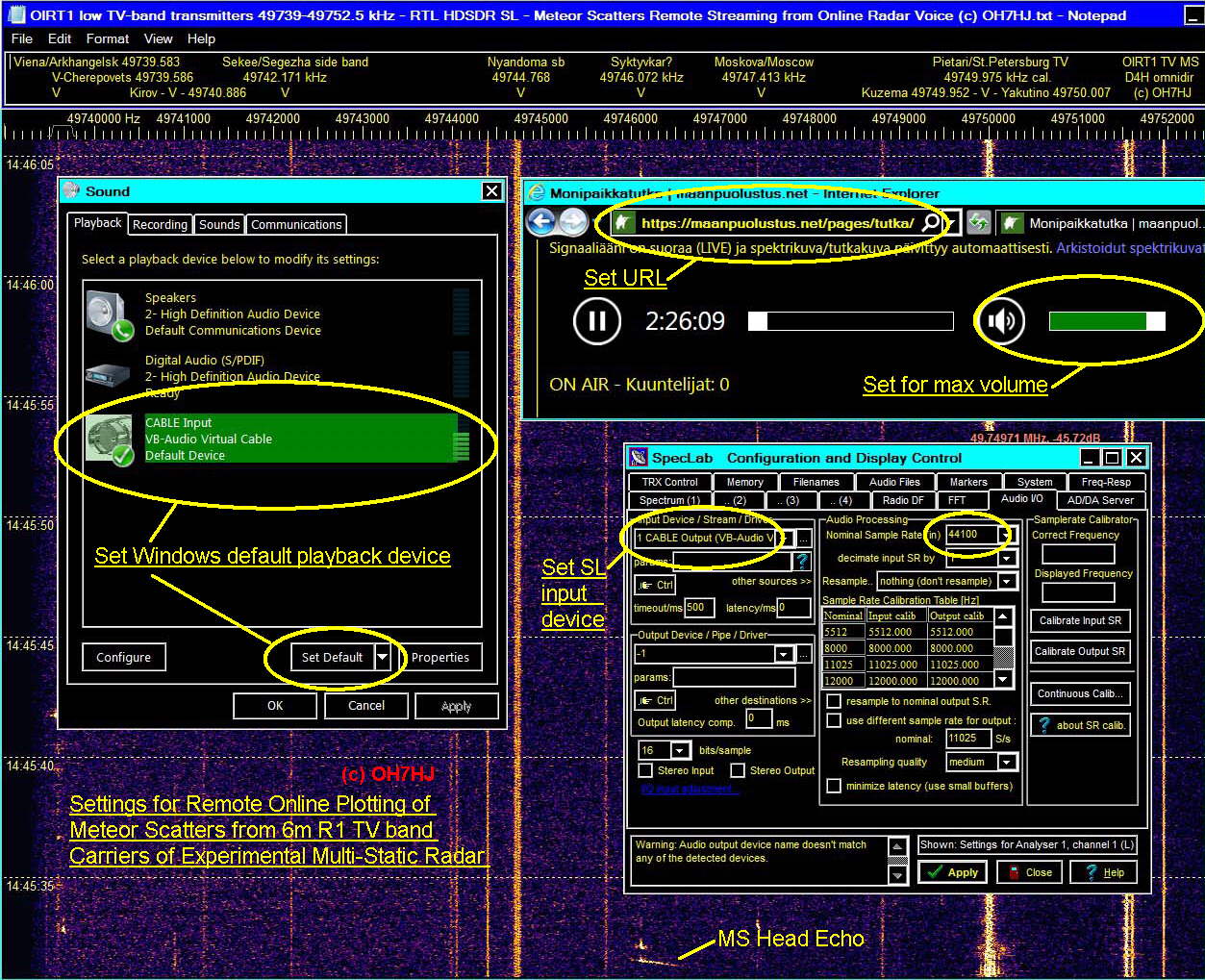
Eilen pääsin ensi kertaa vertaamaan 6m auroraheijastusta suunnilleen keskenään vastaavien vaaka- ja pystyantennien kesken. Majakoina olivat 6m bandin R1-kanavan TV-lähettimet, jotka lähettävät pääasiassa vaakapolarisaatiossa. Vaaka-antennina oli 4-elementtinen, suuntakuvioltaan dipolia vastaava kaksikeilainen dipolimatto D4H, jonka pääsäteilysuunnat ovat koilliseen ja lounaaseen. Vertailupolarisaation antavana pystyantennina oli puolestaan 4-elementtinen koilliseen suunnattu vertikaalijagi Y4V. Vastaanottimina olivat tavalliset RTL-tikut, tosin bandifiltterien läpi kuuntelevina, ja softina SDR V3 ja Spectrum Lab. [/b]

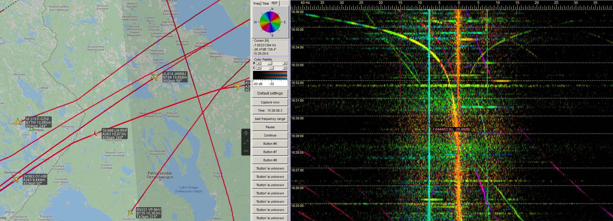
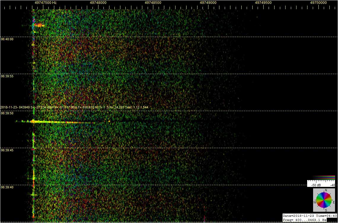
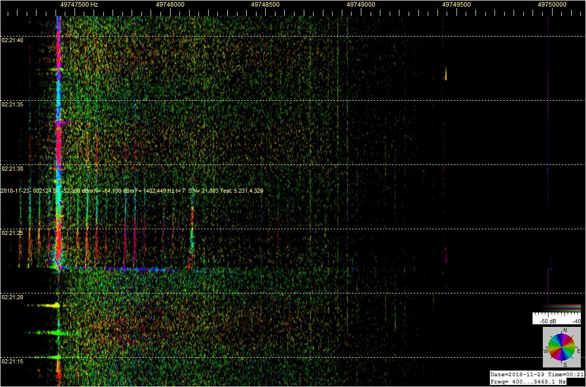
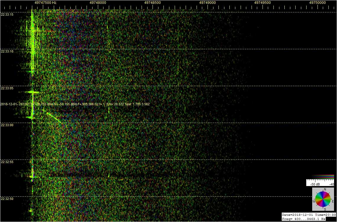
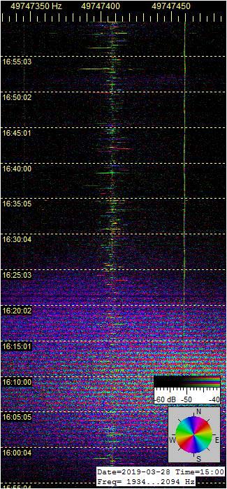
Revontuli- eli aurorapurkauksen kohinaisena ‘lumisteena’ nauhoilla näkyvä heijastusspektri leviää voimakkaasti. Auroraheijastus onkin yksi kaikkein korkeimmalla tapahtuvista voimakkaista sähkönpurkausheijastuksista (EDS). Minkä korkeammalla yläilmoissa sähkönpurkaus tapahtuu, sen leveämmällä hajaspektrillä se moduloi heijastuvaa radioaaltoa. Alkuvaiheen aurorapurkauksissa kohinaspektri näkyy nauhoilla yleensä oikealla, eli korkean dopplersiirtymän puolella. Korkea dopplersiirtymä merkitsee yleensä havaintovastaanotinta lähestyvää aurorarintamaa.

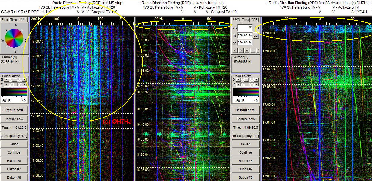
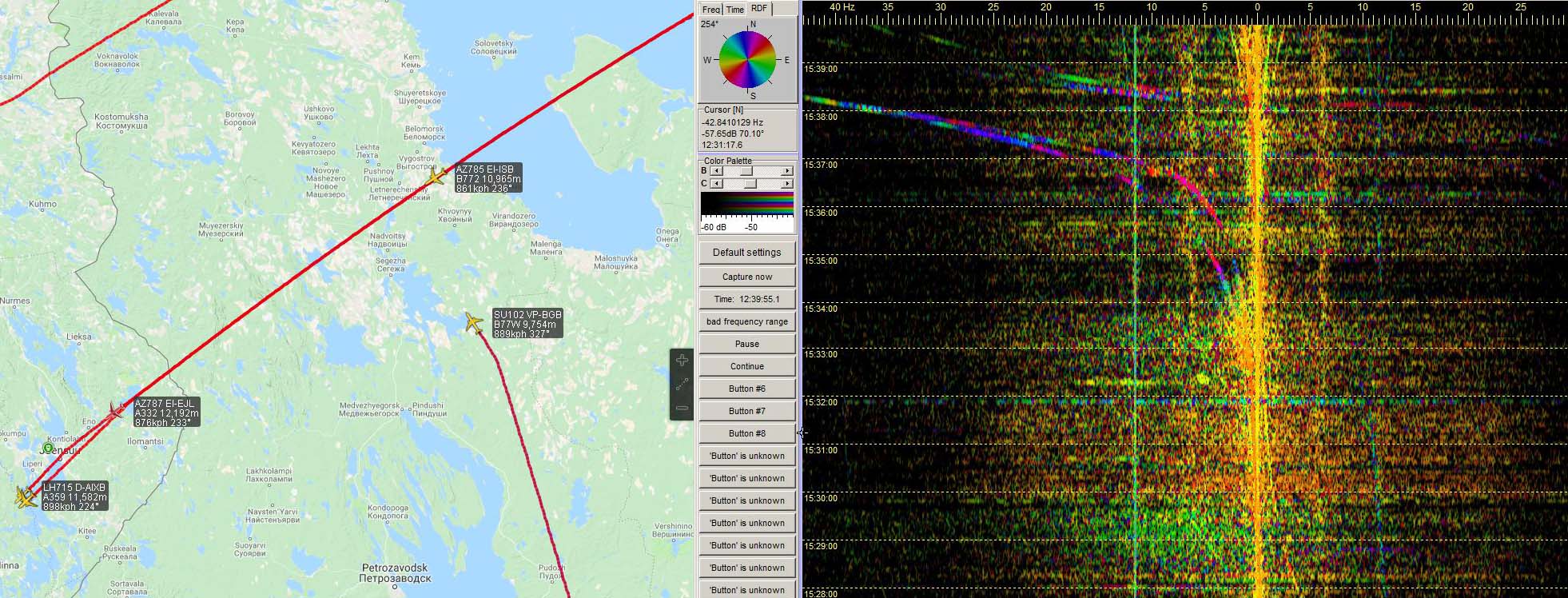
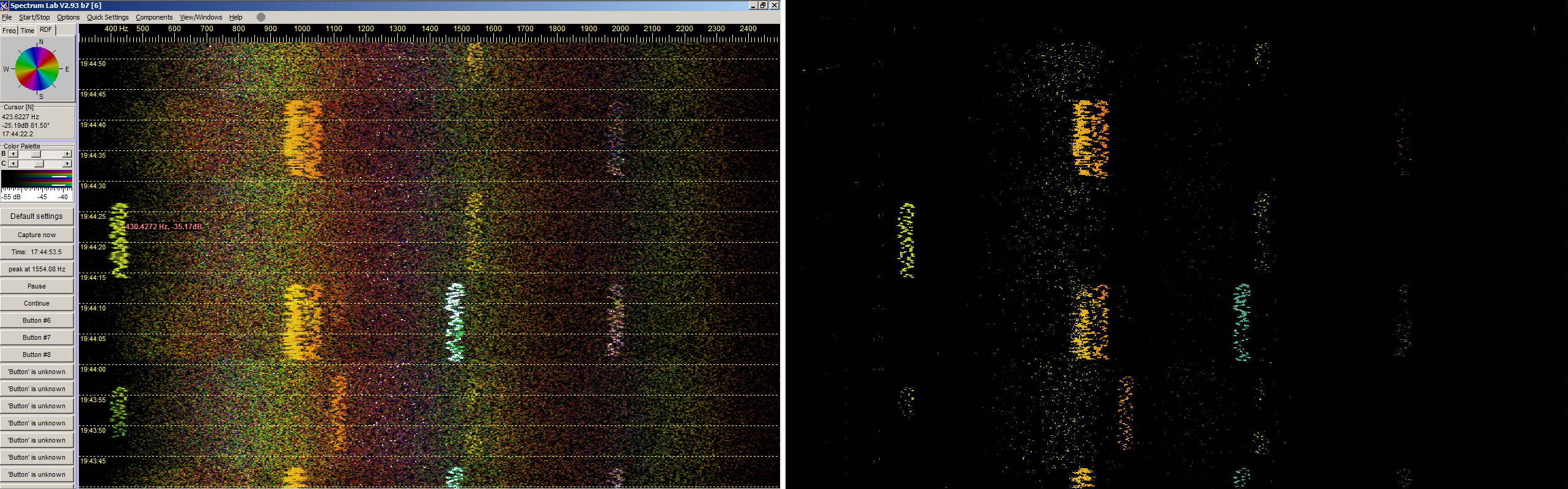
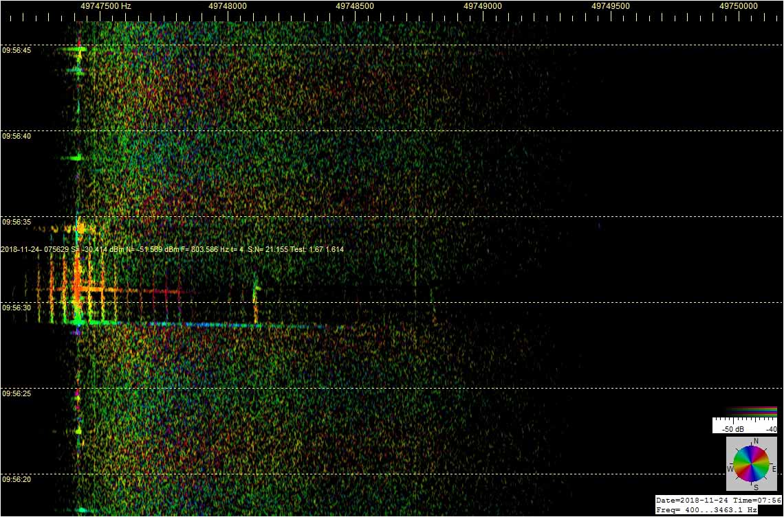
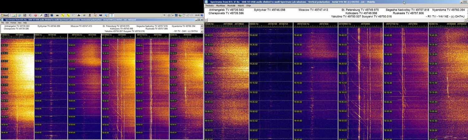
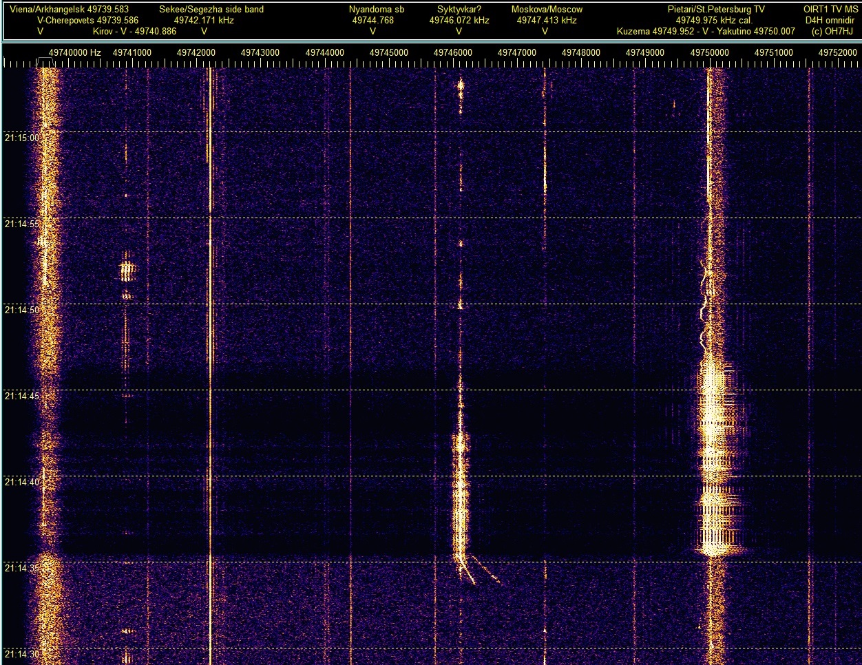
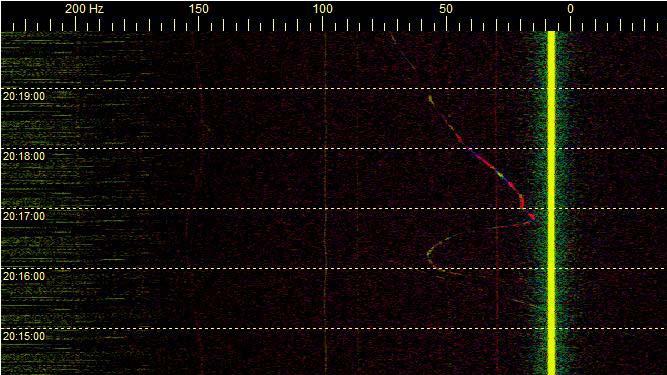
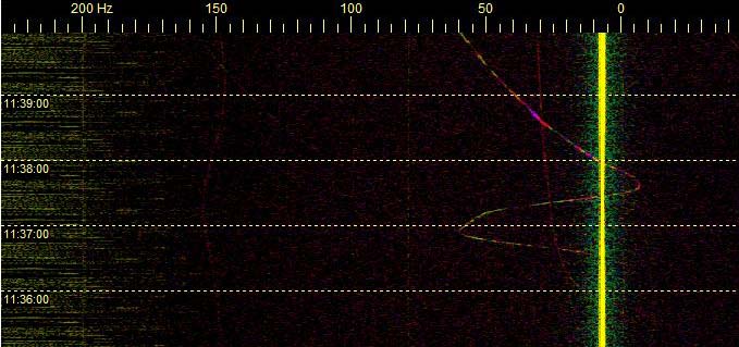
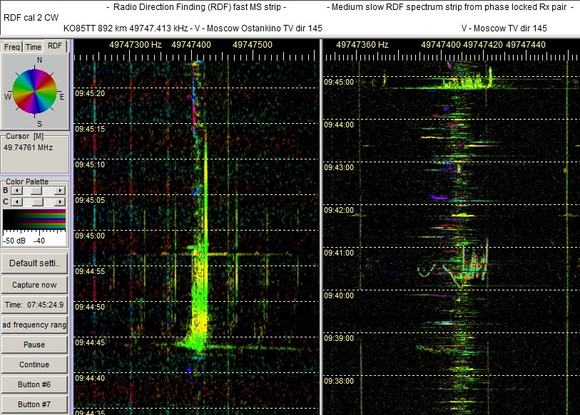
Ensimmäisissä kahdessa liitekuvassa näkyvät Spectrum Labilla zuumatut yksityiskohtanauhat auroran kautta yleensä voimakkaimmista R1-kanavan TV-lähettimistä. Ensimmäisessä kuvaparissa ovat TV-asemien spektrit aurorapurkauksen alun aikana, vaaka-antenni vasemmassa pienemmässä ruudussa, ja vertikaali oikeassa isommassa. Näistä vertaamalla selviää, että vasemmanpuoleisella horisontaaliantennin spektrinauhalla auroraheijastusten ‘lumisateena’ näkyvät hajaspektrit ovat voimakkaampia. Tuore alkuvaiheen aurorarintama heijasti siis ainakin tässä kokeessa horisontaalipolarisaatiota voimakkaampana.

Ensimmäinen kuvapari: 2018-12-07-1943 FT - Savo-M polarimetry - Comparing D4H to Y4V NE - Aurora © OH7HJ.jpg

Auroran hajotessa polarisaatio kääntyi

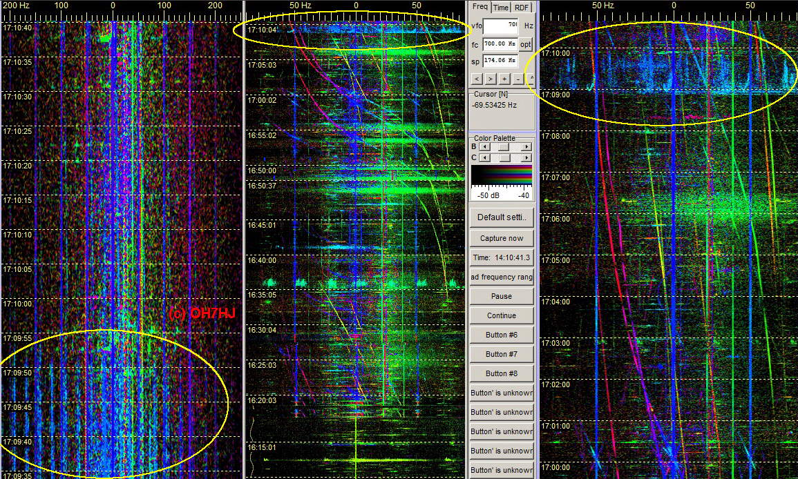
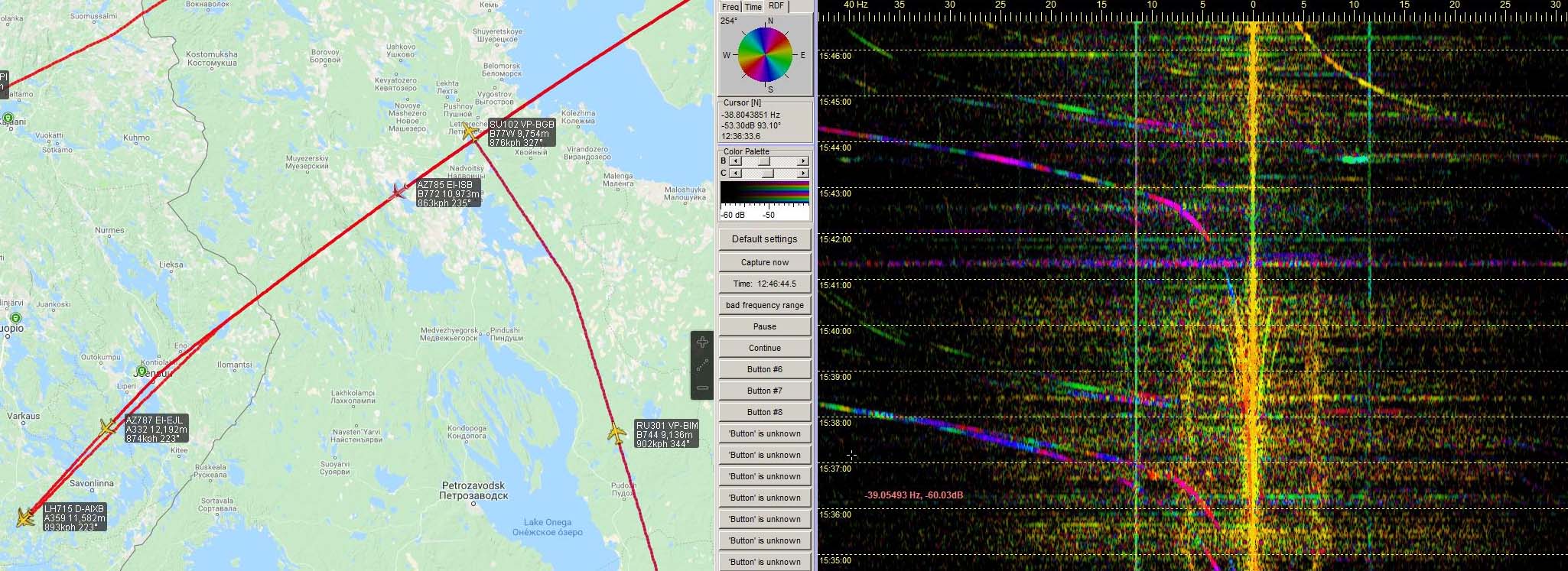
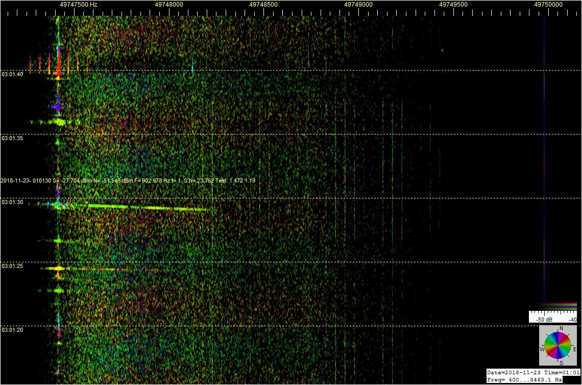
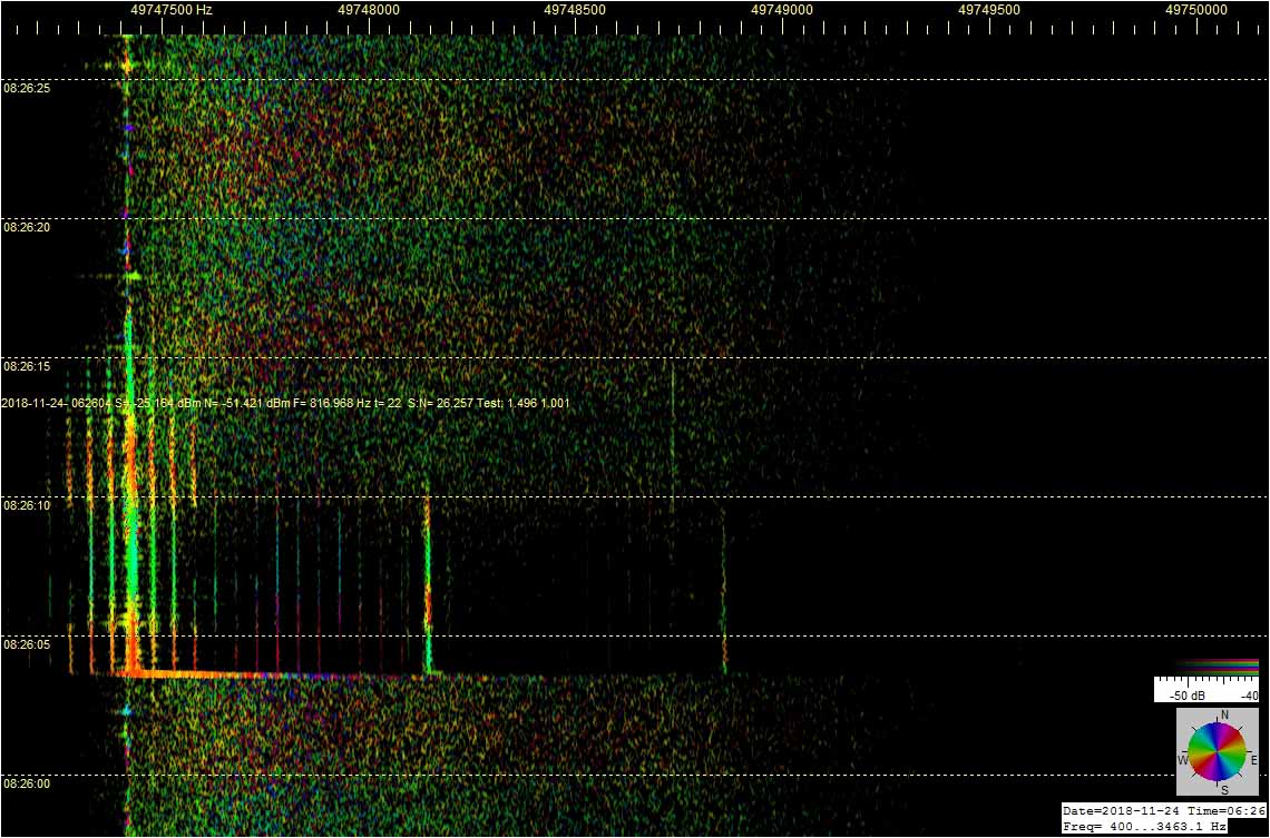
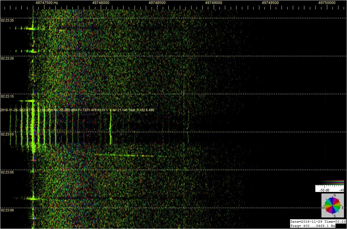
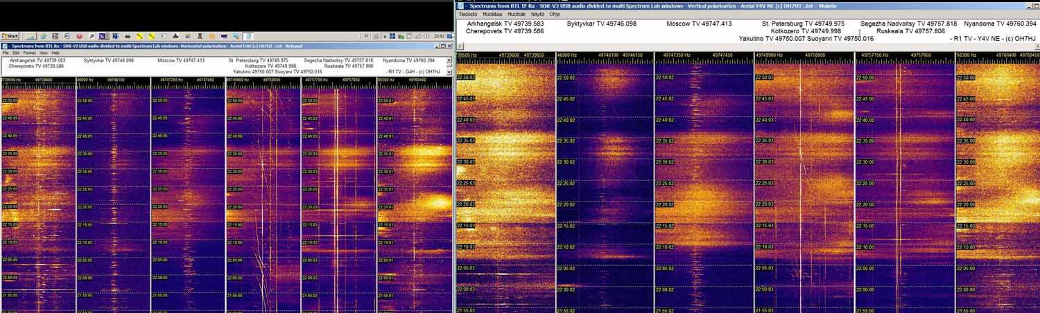
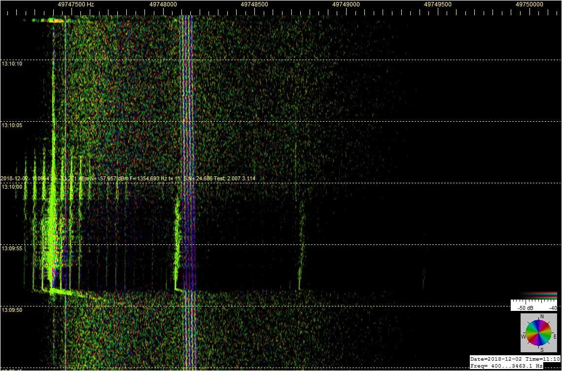
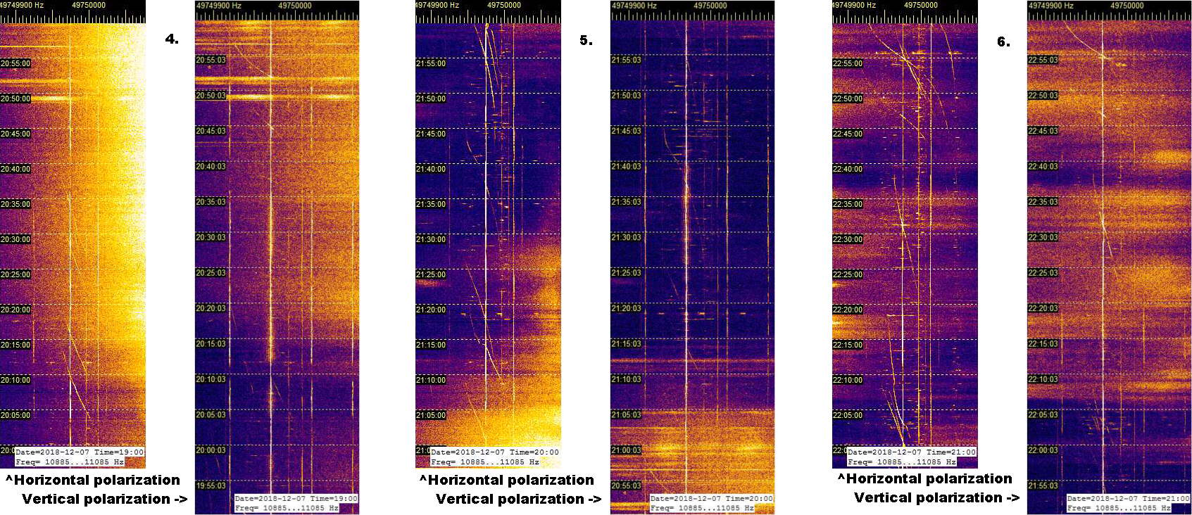
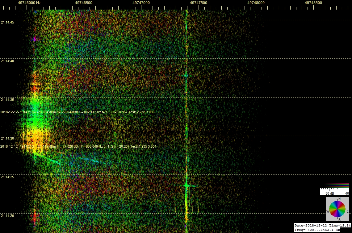
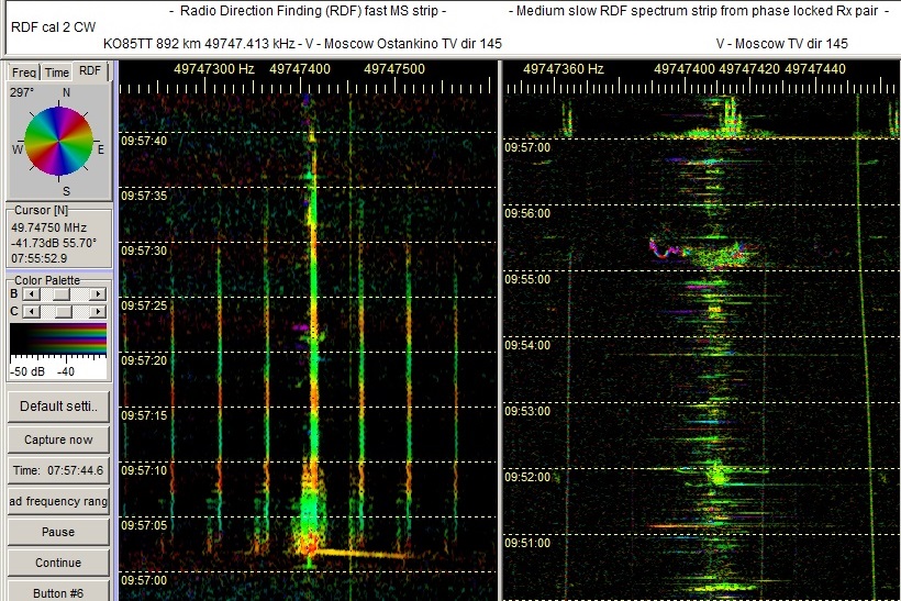
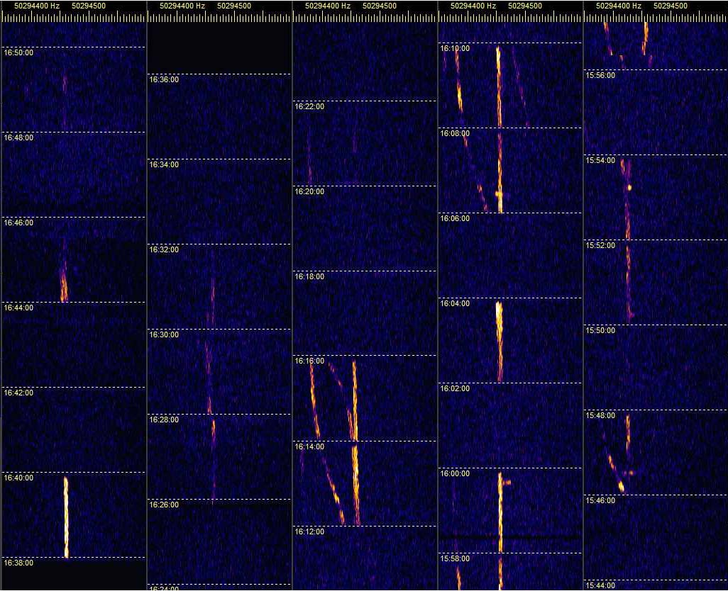
Toisessa liitekuvassa näkyy, miten aurorapurkauksen leimahtelevan ja pyörteilevän loppuvaiheen aikana sen voimakkaimmin heijastaman radioaallon polarisaatio näyttää kääntyneen. Tälle revontulipurkauksen hajoamista ennustelevalle loppuvaiheelle ovat ominaisia spektrinauhoilla näkyvien ‘auroralieskojen’ dopplersiirtymän villi vaihtelu korkean ja matalan, eli nauhoilla niiden oikean ja vasemman reunan välillä. Silmin nähtynä tätä revontulten vaihetta kuvataan usein ‘tanssiviksi’ revontuliksi.

Otosparin oikeanpuoleisen ruudun vertikaaliantennilla 6m R1-TV-kanavan lähetinten revontuliheijastukset alkoivat näkyä voimakkaampana, kuin vasemman ruudun vaaka-antennin näkemät auroraheijastukset. Aurorassa saattaa siis tapahtua polarisaation hajoamista ja kiertymistä radioaallon heijastuksessa ainakin tällä 6m VHF-alabandilla?

Toinen kuvapari: 2018-12-07-2252 FT - Savo-M polarimetry - Comparing D4H to Y4V NE - Aurora © OH7HJ.jpg

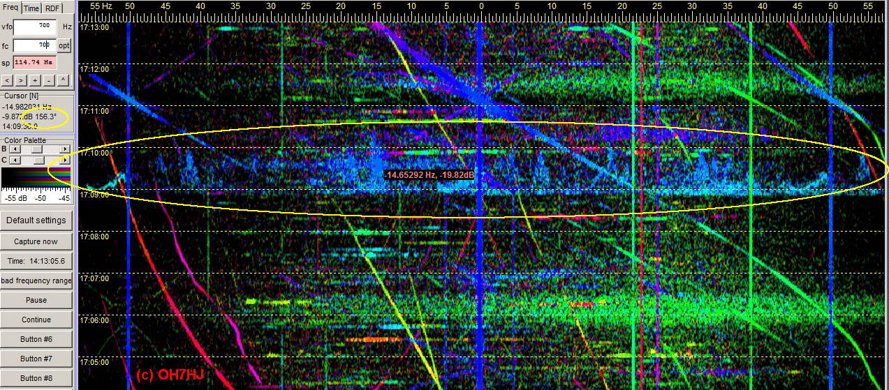
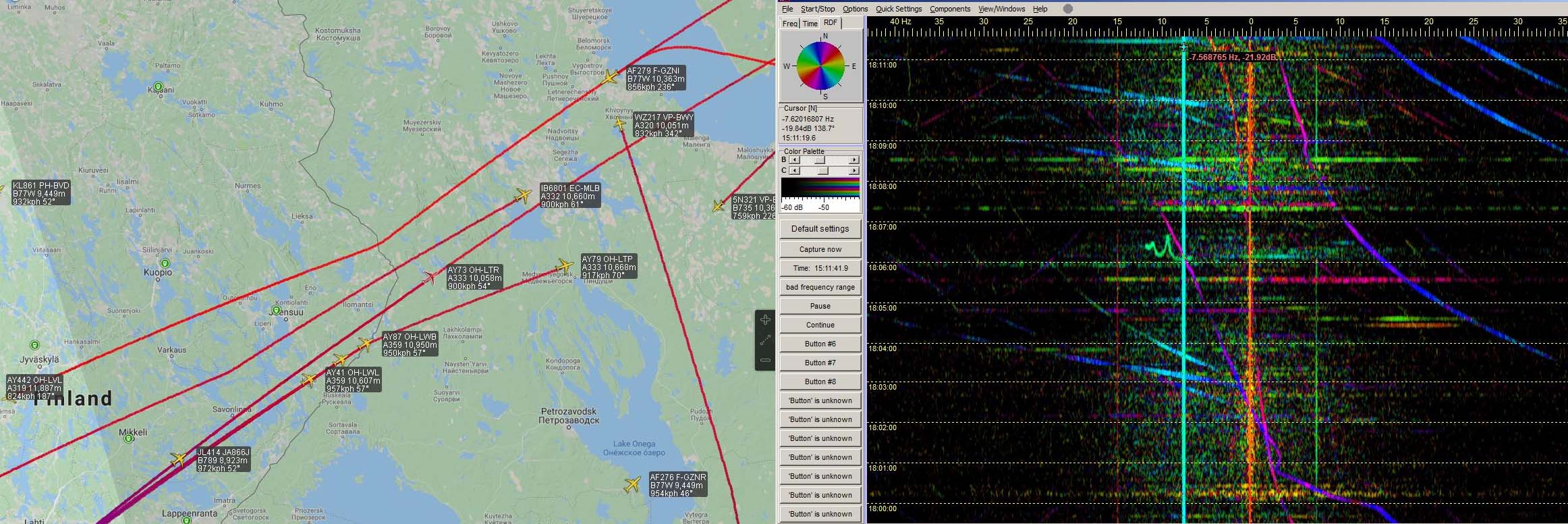
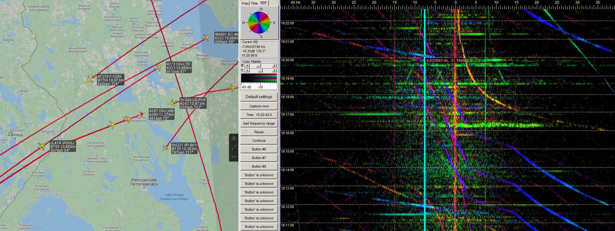
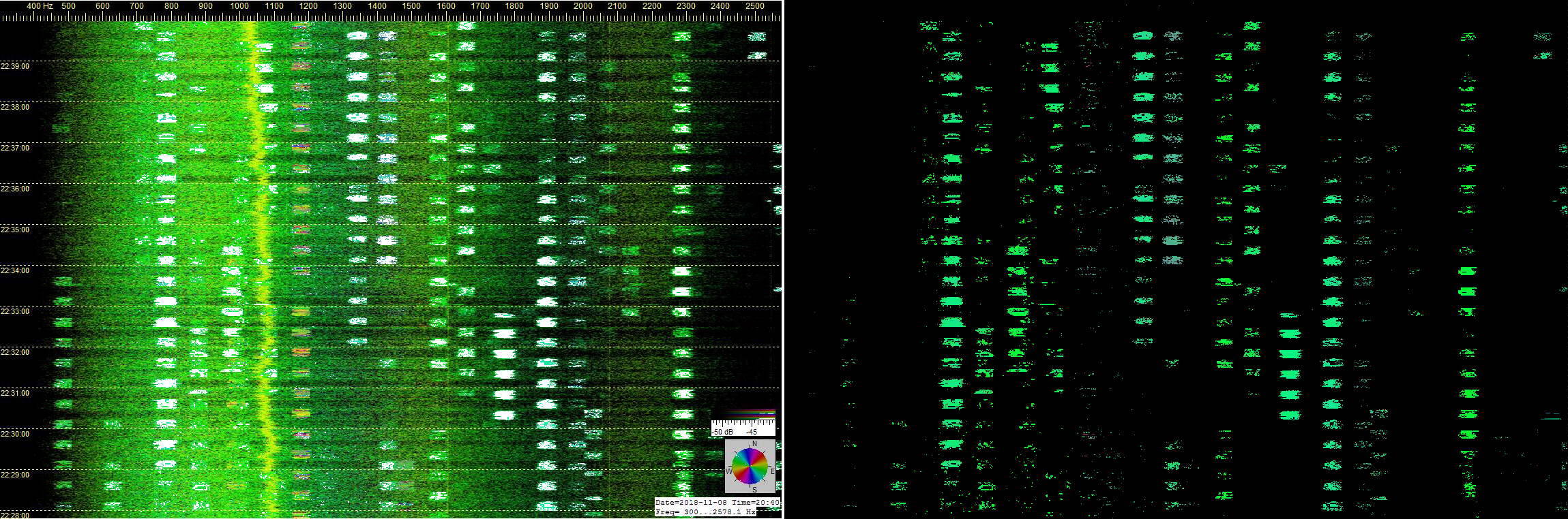
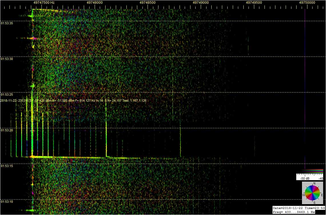
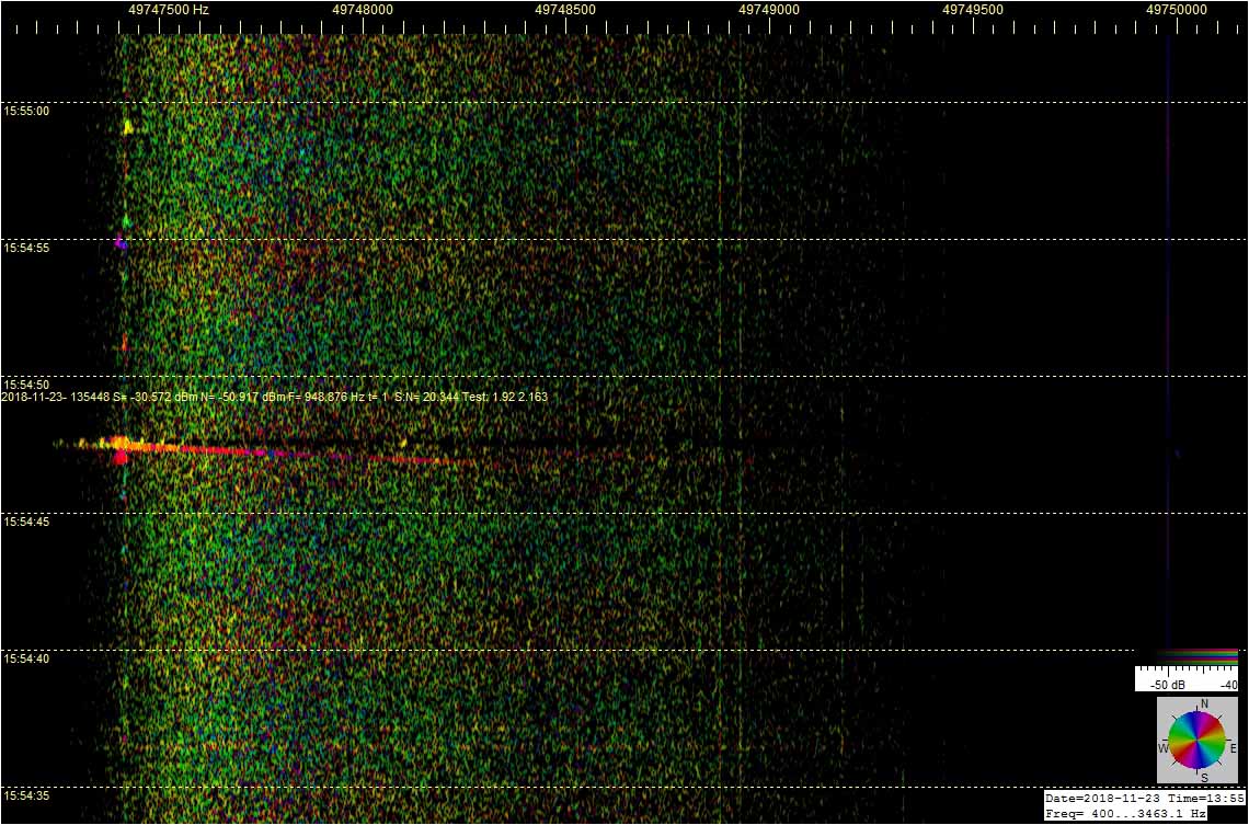
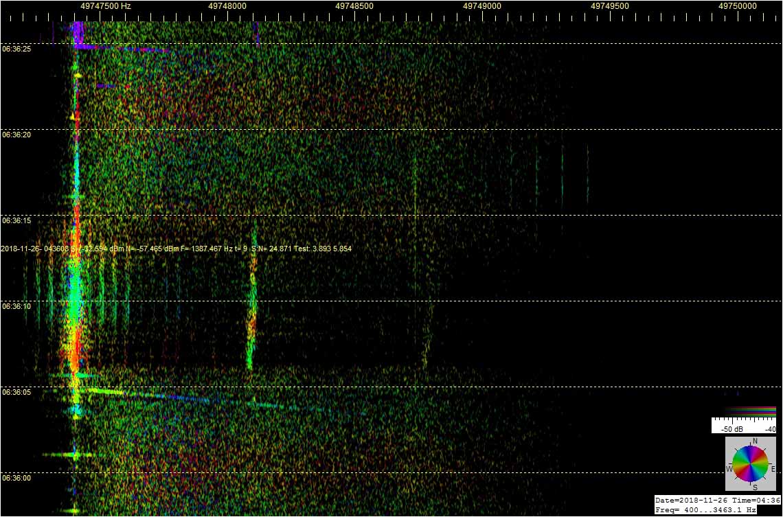
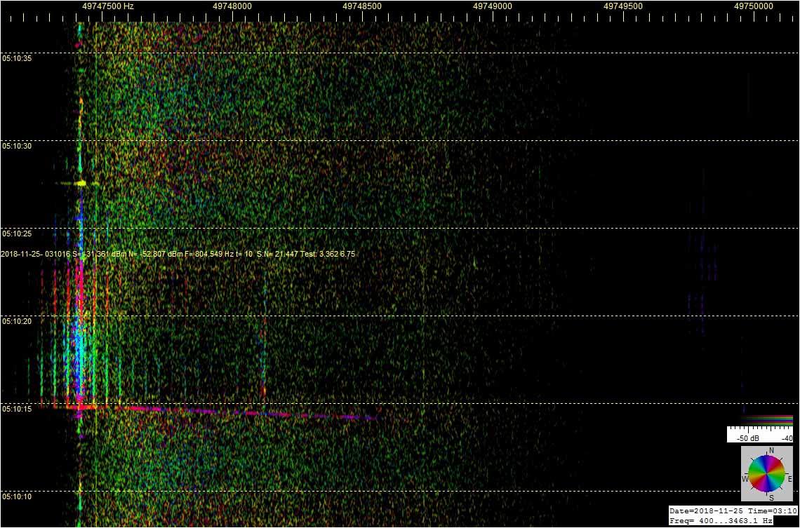
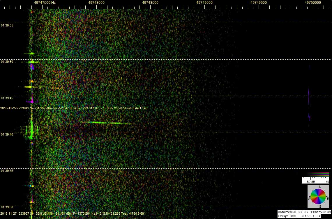
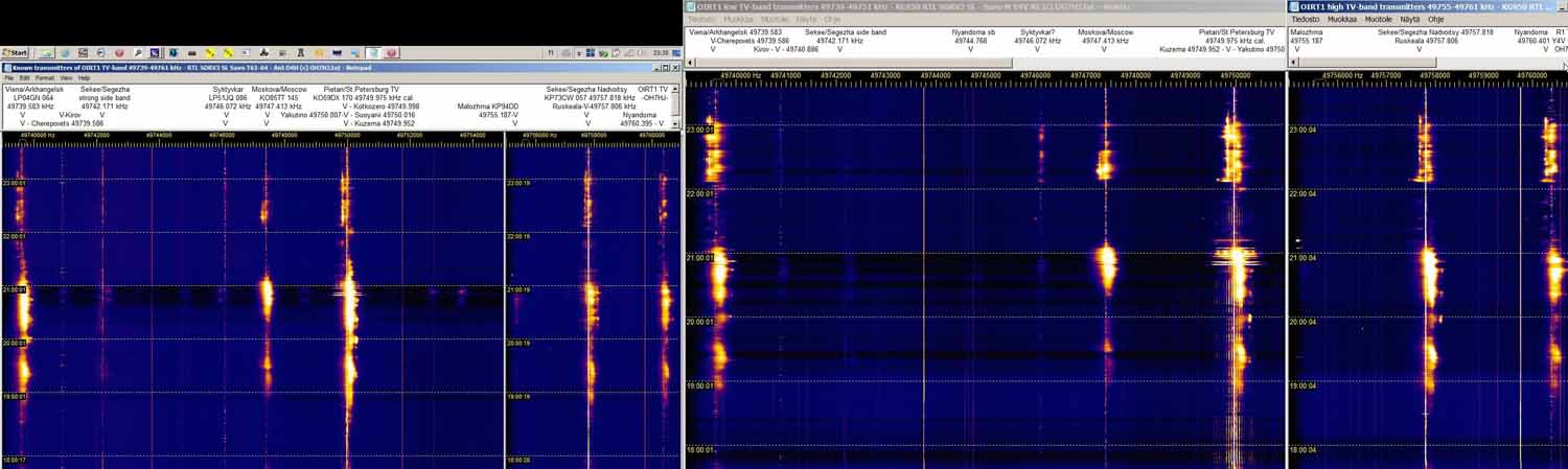
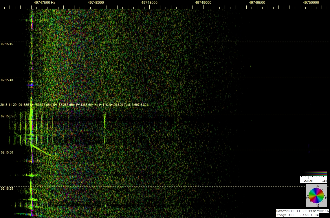
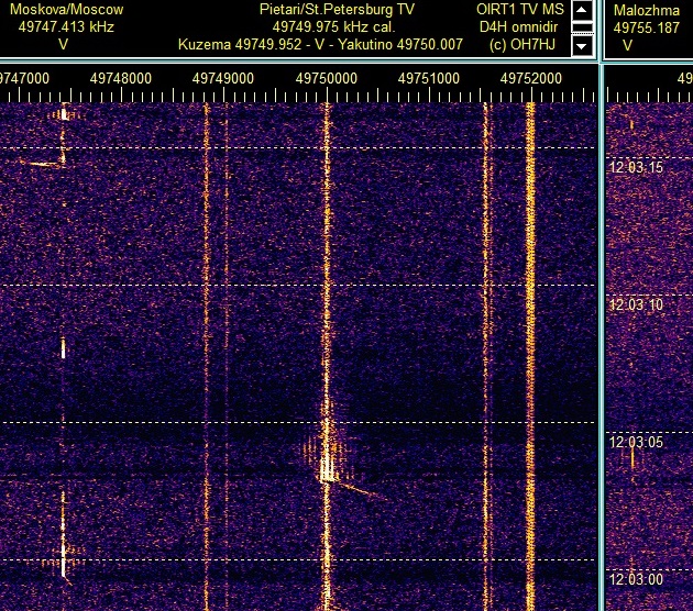
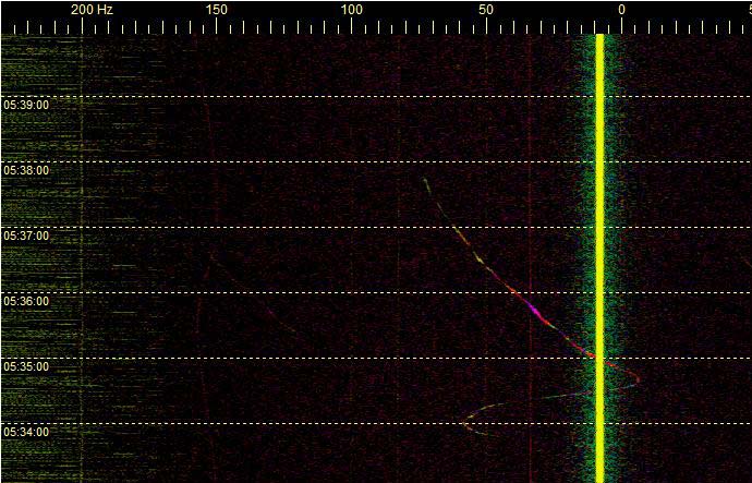
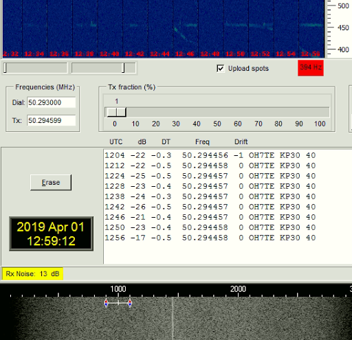
Kolmannessa liitekuvassa on vertailun vuoksi samasta aurorapurkauksesta hitaan spektrinauhan tallenne ‘raakana’ jatkuvana R1-TV-kanavan spektrinä. Siinäkin näkyy auroraheijastuksen voimakkuuden kasvu oikeanpuoleisen kuvan vertikaaliantennilla purkauksen loppuvaiheessa, eli nauhoissa ylhäällä.

Kolmas kuvapari: 2018-12-07-2335 FT - Savo-M polarimetry - Continuous R1 spectrum view - Comparing D4H to Y4V NE - Aurora © OH7HJ.jpg

Mistä pystypolarisaatio auroraheijastukseen?

Aurorapurkauksen alun voimakkaimmin vaakapolarisaationa heijastuvaa aalto on ymmärrettävä, koska kaikki voimakkaimmat 6m R1-kanavan TV-lähettimet lähettävät horisontaalina. Polarisaation kiertyminen loppuvaiheen aurorapurkauksessa on vaikeampi ymmärtää. Kun ajattelee revontulipurkauksen syntytapaa suurjännitteisenä sähkönpurkauksena ionosfäärin ja voimakkaasti varautuneen aurinkotuuliympäristön välissä olevassa pystysuuntaisessa sähkökentässä, niin ilmiöstä saattaa päästä jyvälle.

Aurorapurkauksen verhomaisen rakenteen muodostavat, suurjännitteisen sähkökentän kiihdyttämien ilmaionien parvet muodostavat pystysuuntaisia ionisaatiovanoja, jotka silloin ymmärrettävästi heijastavat vertikaalipolaroitua radioaaltoa. Kukin lukuisista suurjännitekentässä kiihdytetyistä ilmaioneista muodostaa hetkellisen pystysuuntaisen ionisaatiovanan. Koska aurorapurkauksessa tämä luonnollinen sähkökenttä kiihdyttää lukemattomia ioneja samanaikaisesti, ne yhdessä muodostavat silmillekin näkyvän revontulipurkausverhon pystysuuntaiset säikeet.

Nauhoilla näkyvää radioheijastusta kohinalla hajaspektriksi moduloiva ilmiö saattaa aiheutua revontulipurkauksen lukuisten yhtaikaisesti kiihtyvien ionien radioheijastukseen aiheuttamista dopplersiirtymistä. Silloin hajaspektrin leveys mahdollisesti kuvaa revontulipurkauksen kiihdyttämien ilmaionien nopeusjakaumaa.

Vielä jää selittämättä mahdollinen vaakapolarisaation kiertyminen pystypolarisaatioksi. Samankaltaisia polarisaation muutoksia on aikaisemmin havaittu mm. HF:llä jyrkissä ionosfääriheijastuksissa. Myös auroraheijastuksessahan on kyse jyrkästä takaisinheijastuksesta, eli NVIS. Tällä videolla Matti OH7SV esittelee ionosondiluennossaan radioheijastuksen kiertopolarisaation suunnan jaksottaista vaihtumista HF-alabandeilla: youtube.com/watch?v=AoOoOXNO8K4

T: - Juha OH7HJ

Kaikkia liitekuvia on voimakkaasti pienennetty, että ne mahtuvat nettisäikeen kokorajoihin. Sri mittaustietsikoiden eri kokoisista näytöistä johtuva vaaka- ja pystypolarisaatioruutujen kokoero!


[b]In English:

6m Band Aurora Scatter Shifted its Polarization

Setting up multi Spectrum Lab windows with different settings sharing and plotting from the same signal source it is easy to monitor simultaneously as well high speed meteor scatters as slower natural high sky scatters. In this experiment I did a simple polarimetric comparison of 6m band R1 channel TV carriers scattering back from aurora (Aurora Borealis, Northern Lights) discharge front. [/b]

The result of the observation was that at least this aurora discharge scatter (ADS) appeared to shift the dominating polarization of 50 MHz scatter from horizontal at discharge early stage to vertical at its late stage.

Natural high sky electric discharges like ionospheric lightnings appear to modulate radio waves scattering from them with noise, creating a characteristic spread noise spectrum of electric discharge scatters (EDS). These multi-static radar observations suggest that high altitude natural electric discharge radio scatters on low VHF have a wider distinctive spectrum spread than those scattering from lower altitude discharges like Es.

Aurora Scatter Phases

As a very high altitude discharge the aurora discharge scatter has very wide spread noise spectrum. In the beginning and early stage of the aurora discharge it scatters 6m wave usually with high doppler shift which makes the aurora spread noise spectrum ‘cloud’ appear rather steadily to the right of TV carriers at these strips. This may indicate aurora discharge front gradually spreading from North to South towards the observing receiver.

Later as the aurora discharge has ceased spreading southwards it shifts to the latter stage of rather rapidly flaring discharges. Aurora watrchers usually describe this latter phase as “dancing Northern Lights”. On the spectrum strips the aurora noise spectrum shifts wildly between high and low doppler shifts every few minutes. Eventually the discharge fades out.

Using aerials roughly comparable by their gains towards aurora front, the early phase of aurora discharge scatter appeared to reflect horizontal ADS with stronger signal than vertical. This is easy to understand because majority of R1 TV Tx’s are horizontally polarized. However, at the latter flaring phase of the aurora it started to scatter vertical polarization stronger. This polarization shift is more difficult to understand.

Polarization Shift Mechanism?

Comparing to HF band ionosonde observations, it is known that on low HF bands the ionospheric backscatter i[/i] wave shifts periodically its circular polarization between right and left hand. So there is regular polarization shift happening in ionosphere. This experiment suggests that aurora discharge backscatter may create similar polarization shifting effects on low VHF as regular ionospheric backscatter does on HF.

I have no access to ‘real’ polarimetry measuring software allowing complete measuring of linear and circular polarizations. So I made the aurora scatter experiment this amateur way as simple comparison between linear polarizations.

Attached are sets of Spectrum Lab strips of early and late phases of aurora discharge scatter. At each there are pairs of screenshots, the left smaller one illustrating horizontal aerial and the right larger one vertical aerial ADS’s. Direction of strip movement is from up to down. Screenshot sizes are strongly reduced and compressed from originals to fit file size limits of attachments.

Regards, - Juha OH7HJ


About locating meteor hits, Esko OH2AYP has introduced me how he is able to define meteor trajectories and areas of impact by combining data from meteor cameras and MS HE dopplers. I can only awe at such math ability!

Every manual MS hit calculation is quite laborous and time consuming so it is practical for those bright fireballs only that attract audience interest. By Esko’s analysis those most spectacular and bright fireballs are created by rather slow meteors. He suggests that slow ones survive long enough to burn at low altitude which makes them easily visible to us on the ground.

Huge majority of meteors are unnoticed by anyone’s eyes, however. For instant locating of all the numerous high sky meteor scatters a network of two or more RDF receiving stations would allow quick initial cross-locating of hits. At least if there were software for it available.

Best Tx’s of Opportunity for MS Head Echo Spotting?

The powerful 6m band TV transmitters are easy for meteor scatter (MS) head echo (HE) spotting because any spectrum software plots nice head echoes on their steady AM carriers. However, 6m aerials are not too common among radio hobbyists and RDF aerials are very rare. What would be good MS observing band with rather high power Tx’s and available for anyone, then?

An obvious choice for MS spotting locating would be common FM BC transmitters. FM tx’s are available everywhere as well as rx aerials, the FM tx’s are powerful enough for MS HE spotting, and they are right at the MS spotting friendly mid or low VHF band. Only thing still needed is receiving software allowing extracting MS dopplers from among the wide frequency modulated (WFM) signal of common BC stations.

There are software for extracting aircraft and other dopplers from FM scatters but these software are not available for us radio hobbyists. Maybe one day someone is able to create FM doppler receiving software for us radio hams, too?

Geminids and Other Slow Meteors

If I have understood it correct the Geminids meteor shower now appearing are supposed to be of asteroid origin? So they should be rather slow ones?

Attached are a few examples of rather mild angle HE dopplers of supposed slow MS hits. There appear to be less these slow ‘mild’ ones than fast meteor dopplers on my spectrum strips. The usual fast ones plot steep HE dopplers almost perpendicular to tx carrier.

Jussi OH7TE kindly calculated with software by Ilkka OH5IY these radiants of Geminids of this month seen from loc KP30HV: Rollerin kierroslukulaskuri

Regards, - Juha OH7HJ -


Toinen auroraheijastuksen polarisaatiomittauskoe. Vertailukuvaparit ovat R1-kanavan Pietarin TV-lähettimen jaksolta. Kunkin spektrinauhaparin 1 … 6 vasemmanpuoleiset nauhat ovat vaaka-, ja oikeanpuoleiset pystypolarisaatiossa olevalta havaintoantennilta.

Kuvapareista 1 … 4 havaitaan, että tämän revontulipurkauksen alku näkyy voimakkaampana vaakapolarisaatiossa. Auroraheijastuksen kohinaisen hajaspektrin dopplersiirtymä on aurorapurkauksen alulle tyypillisesti korkealla puolella, eli näissä nauhoissa oikealla.

Kuvapareissa 4 ja 5 alkaa tasaisemman korkean dopplersiirtymän aurorapurkauksen sekaan ilmestyä lyhytaikaisempia, korkean ja matalan dopplersiirtymän välillä vaihtelevia lyhytaikaisia ‘leimahduksia’, jotka ovat tyypillisiä revontulipurkauksen loppuvaiheelle. Nämä alkavat näkyä yhtä voimakkaana tai voimakkaampina pystypolarisaatiossa, kuin vaakapolarisaatiossa.

Aivan revontulipurkauksen loppuvaiheen nauhaparissa 8. pystypolarisaation näkyy voimakkaampana, aurorapurkauksen vaihduttua sammumista edeltävään tyypilliseen leimahtelevaan vaiheeseensa.

T: - Juha OH7HJ

Johdanto: Revontuliheijastuksen polarisaatiomittaus 6m bandilla - 1. Aircraft Scatter - Lentokoneheijastus ja sen doppleri.


Right now the Geminids slow asteroid meteor shower is showing up on the 6m TV band multi-static radar strips with mild angle head echo (HE) dopplers of meteor scatter (MS) hits. While many MS ‘tails’ are plotted as short narrow upright lines on spectrum strips, there are also many that create longer and wider spread spectrum ‘furry’ noise modulated tails. Looking at the rather slow mild angle MS HE dopplers, many of them have a narrow spread spectrum EDS tail, while high velocity meteors with steep angle dopplers usually create wide spread spectrum ‘furry’ EDS tails.

The ‘furry’ wide noise MS tails may be caused by meteor ionized track or ‘tail’ creating a shortcut between high voltage charged spots of ionospheric layers and triggering a high voltage ionospheric discharge. These noise modulated electric discharge scatters (EDS) appear to have wider spectrum spread when occurring at high altitude. Correspondingly, narrow spectrum spread EDS tails seem be created at lower altitudes.

Quite naturally, high velocity steep angle doppler meteors tend to ‘burn’ in high altitudes, while low velocity mild doppler angle meteors survive deeper to lower altitudes of atmosphere. This leads to an obvious conclusion that fast meteors are usually associated with wide spead spectrum EDS tails because they create trail high and slow ones have narrow spread spectrum EDS tails because they draw their tracks lower.

Attached are examples of recent MS hits with mild angle and steep angle HE dopplers. These have been captured from the online radar voice stream on oh7ab.fi/foorumi/viewtopic.p … =210#p2635

Regards, - Juha OH7HJ

Please click pics to expand them!


Erikoinen kaksoisosuma taivaankivestä. Sama oli tallentunut sekä radiosuuntimon (RDF), että nettitutkan (remote stream) antenneilla. Loivat dopplerit, eli hitaansorttisesti ovat lentäneet, ehkä aitoja asteroidin sukuisia geminiidejä?

Pörröinen sähkönpurkaushäntä eli hajaspektri merkinnee, että kohtuullisen korkealla on vetänyt vanaa. Alemmassa radiosuuntimon otoksessa doppleri vaihtaa väriä, eli on vetänyt melko pitkän viirun yli taivaankannen, koska suuntima on muuttunut lennon aikana.

T: - Juha

Klikkaa kuvat auki:


Examples of dopplers from a close airport on its 2m ATIS beacon. Quite as expected, low flying aircraft dopplers on takeoff and approach are visible because close horizon does no more limit visibility although ATIS beacons have rather low power of about 10 watts or so. The 6m TV transmitters explained with earlier doppler experiments allow to observe only rather high flying aircraft because these TV transmitters are far away beyond horizon.

A few of these takeoff dopplers are visible almost from the beginning as they extract from the ATIS Tx. The ATIS beacon carrier visible about as vertical line on the Spectrum Lab strips. This suggests that in optimal cases close to Tx aircraft can be observed from very low altitudes.

I do not have a radio direction finding aerial for 2m ATIS band so I am using the incorrect 6m crossed loop XQ4H. With it the Spectrum Lab plots dopplers with their colors varying by their direction of arrival but their RDF directions are not calibrated because of ‘wrong’ band of RDF aerial.

Regards, - Juha OH7HJ
SL5 RDF ATIS Joensuu - XQ4H 6m (c) OH7HJ - 2018-12-23-1819 - Takeoff doppler seems begin from ATIS carrier.jpg
SL5 RDF ATIS Joensuu - XQ4H 6m (c) OH7HJ - 2018-12-24-0939 - Takeoff doppler visible from ATIS carrier.jpg
SL5 RDF ATIS Joensuu - XQ4H 6m (c) OH7HJ - 2018-12-24-0339 - Takeoff doppler.jpg

Meteors are triggering nice high sky discharge scatters today. At left on Spectrum Lab fast RDF strips a meteor scatter head echo (MS HE) doppler is followed by a strong tail scatter.

At center is a TV carrier and on its both sides are side bands of the 6m R1 channel Moscow TV at 49747.4 kHz. The slower SL strip at right illustrates curious ‘doppler hooks’ of MS tail electric discharges. The doppler 'hooks or ‘fork’ scatters may be created by high altitude discharges with their streamers dividing to two or more directions.

When there are a lot of these kind MS triggered electric discharge scatters (EDS) there may appear also low VHF ionospheric radio propagation like aurora scatter or thunderstorm Es.

Experiment: Aerial is a radio direction finding (RDF) crossed 2x4-element skeleton quad connected to a coherent pair of FT100D receivers. SL is configured for RDF.


Meteorit liipaisevat tänään kunnon kipunoivia purkauskaaria. Vasemmalla nopealla nauhalla on alhaalla meteorin ‘nokkadoppleri’ (MS HE), ja sen päällä meteorivanan sähkönpurkaushäntä. Hajaspektriäkin on mukana, mikä merkitsee, että purkaus on tapahtunut varsin korkealla.

Oikealla hitaammalla nauhalla erottuu, miten sähkönpurkaushännät (electric discharge scatter, EDS) piirtävät hauskoja ‘dopplerkoukkuja’ haarautuessaan yläilmoissa.

Tällainen taivassähköinen keli ennakoi joskus VHF-radiokelejä aiheuttavia purkauksia, kuten auroraa tai ukkos-Es-keliä.

Yesterday afternoon aurora scatter burst was short but curious. By the radio direction finding (RDF) 6 m radar, two aurora discharges scattered periodically and synchronously from two directions in about 7 second cycles.

Alternating dual path aurora scatter plotted frequent stripes to this RDF bistatic radar receiver slow spectrum strip listening high sky radio scatters at R1 channel Moscow TV frequency: SL2 USB RDF AS Moscow TV - XQ4H © OH7HJ - 2019-03-28-1500 - Dual path aurora

Signal colors represent directions of incoming wave. The accompanying RDF color circle suggests that these alternating dual path aurora scatters propagated from northeast and northwest.

A fast RDF spectrum strip of the bistatic radar experiment reveals details of the regularly alternating dual path aurora scatter: SL5 USB RDF XQ4H Syktyvkar MS Moscow TV OH7HJ UTC 2019-03-28-141333 - Dual path aurora

Origin of Northern Lights by Bistatic Radar Observations

Aurora discharges are propelled globally by the same high voltage source of electricity as any other atmospheric electricity: The charged solar wind.

High voltage aurora discharge ‘ground’ is the rim of ionospheric opening around Earth poles. These polar openings create a natural corona discharge rim for aurora curtain-shaped discharge and the global ‘aurora oval’ shape.

Because aurora discharges have a common ionospheric electric ‘ground’, it is possible that separate aurora discharges from common aurora oval rim may alternate synchronously like they are doing by this bistatic RDF radar observation.

Setup: Spectrum Lab is configured for RDF. Aerial is a radio direction finding (RDF) crossed quad combined from 2x4-element skeleton quad driven elements, each connected to a coherent pair of FT100D receivers. Pic: download/file.php?id=1407


Jaksottaisesti vuorotteleva kaksitieauroraheijastus

Eilisen iltapäivän aurorapurkaus oli lyhyt ja vaisu, mutta siinä esiintyi erikoinen luonnonoikku. Aurorapurkauksen tavanomaisessa hajaspektrissä näytti vuorottelevan keskenään tahdistetusti kaksi auroraheijastusta eri suunnista oheiskuvien Moskovan TV-taajuudella.

Jaksottaisesti noin 7 sekunnin välein vuoroa vaihtava kaksitieauroraheijastus näkyy radiosuuntimon hitaalla nauhalla ‘marianneraitoina’, ja nopealla nauhalla suunnan mukaan väriä vaihtavina ‘savumerkkeinä’.

Jännästi ovat auroralieskat tahdistaneet itsensä vuorottelemaan. Suuntimavärien perusteella mahdollisesti toinen luoteessa, ja toinen koillisessa.

Samalla varatun aurinkotuulen suurjännitteisellä sähkönlähteellähän revontulipurkaukset ainakin tutkahavaintojen perusteella toimivat, joten ne voivat hyvinkin vuorovärähdellä tähän tapaan, kun purkausten yhteisenä sähköisenä maana on ionosfäärin napa-aukkojen reuna?

Aircraft scatter experiments with WSPR narrow band AFSK digi mode on 50293 kHz USB.

Transmitting station OH7TE has a low dipole and about 200 W power.

Receiving station OH7HJ is located 249 km away listening with a 2 x 6 el yagi 23 m above ground.

Curved scatters on strips are aircraft scatter dopplers. Short scatter dots are natural high sky MS tail and EDS scatters.

Links:

Lentsikkadopplereita 6m WSPR:llä - Aircraft Scatters on WSPR - Osa 1. - viewtopic.php?f=21&t=295&p=1150#p1150

WSPR maps - wsprnet.org/drupal/wsprnet/map