Aircraft Scatter - Lentokoneheijastus ja sen doppleri.

Tässä leimahtelevien revontulten ‘lieskat’ saavat muodon radiokaikuina. Harrastajavoimin toteutettu revontulitutka kertoo revontulipurkausten suuntien vaihtelut muuttuvina väreinä Spectrum Lab -softan Radio Direction Finding (RDF) -toiminnon avulla.

Tutkaotoksessa oikealla ovat ‘raakanauhat’ kahdelta eri antennilta, joista spektrisofta laskee keskellä näkyvälle nauhalle suunnat väreinä. Vasemmanpuoleisin nauha on tarkoitettu nopeiden ilmiöiden seurantaan.

Revontulipurkausten luonnollisten liikkeiden mukana niiden kohinana kuuluvat ja ‘lumisateena’ spektrinauhoilla näkyvät kaiut liikkuvat dopplersiirtymän johdosta nauhoilla oikealle ja vasemmalle. Seassa näkyvät ohuet kaaret ovat lentokoneiden dopplerkaikuja ja pystysuorat viivat TV-lähetteitä. Aikaleimat nauhojen reunoissa ovat Suomen aikaa.

In English: Flaming Northern Lights on radar spectrum strips. The passive ‘Aurora Radar’ is built by radio hobbyists. It shows directions of high sky Aurora discharge flares as changing colors.

Two separate receiving aerials are used to get the directions of radio waves bouncing back from Northern Lights (Aurora Borealis) discharge front. The ‘snowfall’ like noise clouds on radar strips are radio waves scattering from the aurora discharge flares that are constantly igniting, moving and fading on the ‘Aurora Oval’, a discharge front around Earth poles.

Links:

Uusimmat kuvat monipaikkatutkasivulla - Updating multi-static radar online demo page: maanpuolustus.net/pages/tutka/
Aurora Scatter on RDF Strips - Revontulipurkaus: OH7RUB liittäminen R.NET -verkostoon ?
Birth of Aurora Discharge on Fast RDF Strips: OH7RUB liittäminen R.NET -verkostoon ?

T: - Juha


By the article “Limits on radio emission from meteors using the MWA” it looks like formal science is opening its eyes to the spread noise spectrum natural scatters that amateurs have been spotting and explaining for years?

… “broadband radio emission has been observed accompanying bright meteors” …
“The broadband spectra between 20 and 60 MHz were captured” …
… “with a usable bandwidth of 75 kHz tunable to any centre frequency between 10 and 88 MHz. These two events lasted for 75 and 100s, respectively, at 37.9 and 29.9 MHz” …

The pics on paper are not similar spectrum analyzer strips familiar for us with high sky scatter spotting but these quotations suggest that there is something similar on low VHF that they are observing. There is something related to explaining birth of the spread noise spectrum scatters that the article authors appear to miss.

Spread Spectrums by Electric Discharges

Electrostatic experimenters know that scattered radio wave spectrum spread is a characteristic mark of radio waves scattered from air ions accelerated by electrostatic discharge. A high voltage discharge in low pressure gas creates ionization or plasma which modulates scattering radio waves by a noise spectrum.

One may suppose that high atmosphere spread spectrum scatters are created by natural atmosheric electricity discharges. Usual causes of short electric discharge scatters (EDS) appear to be high sky lightning discharges that seem to be triggered either spontaneously or by ionized meteor trails.

Long lasting spread spectrum scatters on 50 MHz appear to be related to such natural electric events as thunderstorm Es and Aurora discharges, for example.

Attached are examples of short and long spread noise spectrum natural scatters on Spectrum Lab RDF strips at R1 channel Nyandoma TV and Syktyvkar TV Tx frequencies:
RDF MS Syktyvkar TV D4H - Y6H 080 © OH7HJ - 2018-04-27 - Long Spread Noise Spectrum ED Scatters.jpg
RDF MS Nyandoma TV D4H - Y6H 090 © OH7HJ - 2018-04-24-25 - Short Spread Noise Spectrum ED Scatters.jpg

Regards,

  • Juha OH7HJ

Article Link:

Limits on radio emission from meteors using the MWA, 20 April 2018 - arxiv.org/pdf/1804.07060.pdf

[b]Related Links:

50 MHz Spread Spectrum Noise Scatter Observations: [/b]

Aurora precursors on RDF strips - Aircraft Scatter - Lentokoneheijastus ja sen doppleri.
Meteor Scatter ‘Head Echo’ Dopplers - 7. - Aircraft Scatter - Lentokoneheijastus ja sen doppleri.
Meteor Scatter ‘Head Echo’ Dopplers - 6. - Aircraft Scatter - Lentokoneheijastus ja sen doppleri.

Meteor Scatter ‘Head Echo’ Dopplers - 4. - Aircraft Scatter - Lentokoneheijastus ja sen doppleri.
Meteor Scatter ‘Head Echo’ Dopplers - 1. - Aircraft Scatter - Lentokoneheijastus ja sen doppleri.
Spotting MS from among ED scatters - 2. - Aircraft Scatter - Lentokoneheijastus ja sen doppleri.

Spotting MS from among ED scatters - 1. - Aircraft Scatter - Lentokoneheijastus ja sen doppleri.
Strong 6m TV High Sky Scatter - Part 1 - Aircraft Scatter - Lentokoneheijastus ja sen doppleri.
High sky radio scatters sometimes plot curious patterns - Aircraft Scatter - Lentokoneheijastus ja sen doppleri.

Electric Discharge Explanation of Nasa ‘Aurora Arrow’ Photo - Aircraft Scatter - Lentokoneheijastus ja sen doppleri.

Electrostatic Experimenting with Electric Discharges:

Plasma leiskahtaa kurkkupurkissa - guns.connect.fi/innoplaza/energy … index.html
Himmeli lentää sähköllä - guns.connect.fi/innoplaza/energy … nokki.html

Spread Spectrum Articles in Finnish:

Aircraft Scatter - Lentokoneheijastus ja sen doppleri.

Aircraft Scatter - Lentokoneheijastus ja sen doppleri.

Aircraft Scatter - Lentokoneheijastus ja sen doppleri.


RDF tarkoittaa ‘Radio Direction Finding’. Tämä ‘kvadimattoantenni’ (quad array) koostuu kahdesta identtisestä 4-el kvadista puolen aallonmitan päässä toisistaan. Kumpaakin syötetään erikseen samanmittaisilla koakseilla samanlaisille hamssivastaanottimille, jotka on vaihelukittu koherentiksi pariksi. Vastaanottimien äänet syötetään stereoäänikortin kautta tietsikalle, jolla Spectrum Lab -softan RDF-toiminto laskee spektrissä näkyvien radioaaltojen tulosuunnat vertaamalla niiden vaihe-eroa. Kyseessä on siis radiosuuntiminen interferometriamittauksella.

SL erottelee värein kaikki spektrissä näkyvät signaalit niiden tulosuuntien mukaan. Pääsuunnan lisäksi kahden antennin interferometria antaa peilisuunnan. Usean antennin interferometrialla menetelmä tarkkenee, ja kykenee mittaamaan myös saapuvan aallon vertikaalikulman. Radiosuuntimat näkyvät RDF-spektrinauhoilla väreinä tutkanauhakuvan vasemmassa ylänurkassa olevan väriympyrän mukaisesti. Spektrikuvina vasemmalla näkyy nopea RDF-nauha, keskellä hidas RDF, ja oikealla kummankin antennin spektrit erikseen ‘raakoina’ ilman radiointerferometriaa.

Antennin suuntakuvio muistuttaa yhtä vaakakvadia tai -dipolia kaksoiskeiloineen. Kvadiparin sivut on suunnattu Pietarin TV:n suuntaan vaimentamaan vahvaa TV-kantoaaltoa ‘häikäisemästä’ heikkoja dopplereita ja muita taivaskaikuja. Kvadipari on kiinteästi suunnattu, eikä siis pyöri maston mukana. Runkomateriaalina antenniparissa on lasikuituputki. Elementtilankana on eristetty puhelinparikaapeli halkaistuna. Antenniparin korkeus on 6 m, leveys 4,5 m ja paino 5,7 kg.

In English:

A 50 MHz band double 4-element horizontal quad array 2Q4H for interferometry radio direction finding i[/i] lifted up and hanging from a crane built for it to mast. Aerial is made of glass fiber tubes supporting insulated driven ‘skeleton quad’ flexible insulated wire elements. [/b]

High impedance quad arrays are matched to their 75 ohm TV coaxes with 120 cm sections of 105 ohm twin lead. Quad pair dimensions: Height 6 m, width 4.5 m and weight 5,7 kg. Both RDF 4-el quad sets of the identical pair are connected with feed coaxes of same length to similar ham receivers which are phase locked to create a coherent pair. The audios from the receivers are fed to computer stereo sound card inputs and analyzed with Spectrum Lab (SL) software RDF option.

Resulting SL RDF spectrum strips show signals propagating from different directions with different colors. The direction scales of these screenshots are not yet calibrated. At left is a fast SL RDF strip for spotting short lifetime high sky scatters like meteor scatter head echoes (MS HE) dopplers and spread spectrum electric discharge scatters (EDS) of high altitude ionospheric lightnings. Middle strip is slow for RDF observations of long lasting events like aircraft dopplers, Es and aurora scatter. At right are ‘raw’ input spectrums from both receivers.

4-el pairs of this quad array are a 6m band version of this 2m ‘skeleton quad’ driven elements: guns.connect.fi/innoplaza/juttu/ … index.html

Regards, - Juha OH7HJ


A pair of spacecraft launch dopplers appeared in sound tracks recorded with a standard ham 6m band 6-element yagi antenna and a cheap RTL receiver (Rx). The transmitter (Tx) that had provided the faint but clear fast object dopplers was Moscow TV.

This is surprising because it is one of the most distant of regularly spotted TV Tx’s measured from the spacecraft launch site. However, thinking further, it makes sense.

Moscow Ostankino TV has a high power Tx with about 200 kW ERP power and its transmitting aerial lobes reach high enough from ground far away near the trajectory of the rapidly rising spacecraft, thanks to the long distance and Earth curvature.

Dopplers on Strips:

There are two faintly visible dopplers marked 1. and 2. Please click attached pics to extend them. They show a large enough doppler shift to be created by a departing orbital carrier rocket. Direction of doppler shift is low quite as it should be for a HFO moving away related to Moscow TV Tx. The fading of the dopplers appear distinctive to faraway scatters.

The doppler 1. at left appears to be by its doppler shift from a faster high flying object (HFO) and the doppler 2. at right from a slower HFO. The faster one appears to be created by the accelerating rocket stage and the slower one a jettisoned earlier carrier stage of the rocket.

Attached are copies edited with markings from the recording replay of the 6-el NNE pointing yagi Moscow TV spectrum strips. Time ticks on strips are 15 s apart. Visible time stamps are not calibrated to original observations time because strip is made from a recording.

The Rec-All Pro replay window is showing original observation time as Finnish local (UTC + 3h). Frequency scale is above with Moscow TV carrier position marked. Receiving software was SDR Console V3 and analyzing software was Spectrum Lab.

Rockot - Sentinel 3B Links:

spaceflight101.com/events/rockot-sentinel-3b/
spaceflight101.com/copernicus/tag/sentinel-3/
spaceflightnow.com/launch-schedule/

Regards, - Juha


Short bursts of natural high sky scatters with spread noise spectrum have this far been explained as some kind meteor scatters. However, usually they lack any evidence of meteors so the meteor scatter explanation may be an incorrect guess.

Meteor scatters (MS) are rather easily identified by their narrow spectrum head echoes with their doppler shift indicating high velocity and from their following almost stationary tail scatters.

Contrary to MS, natural electric discharge scatters (EDS) have distinctive spread noise spectrums while their doppler shifts indicate slow movement or stationary position. It is possible that the spread noise spectrums are generated by natural high atmosphere electric discharges modulating radio waves scattering from them.

Sources of Spread Spectrum Radio Scatters?

Thomas Ashcraft has reported simultaneous observations of visible sprite lightnings and low VHF radio scatters. These and other varieties of natural ionospheric lighting discharges may cause these very usual spread spectrum radio scatters.

There appears to be a connection of natural EDS and sporadic E radio scatters (Es) that are very usual here in Europe during May and June. Usually low VHF spread spectrum radio scatters begin as short EDS. These short scatters gradually get longer until they finally create Es bursts lasting from minutes to tens of minutes.

Spectrums of EDS and Es scatters appear usually identical with distictive spread noise spectrum modulating radio transmissions scattered by them. It is possible that both are created similarly.

Thunderstorm as a Source of Es?

A possible cause of these spread spectrum EDS and ES bursts may be high lightning discharges that are known to appear above each thunderstorm cell and front. A short high lightning discharge may be source of EDS bursts.

When lifetime of a high discharge is extended it causes a similar but longer Es burst. Usually these Es burst appear at the same time as a thunderstorm and vanish when the thunderstorm ceases.

Transmitters scattered by Es bursts and heard with our receivers are usually approximately in line with thunderstorms. This may be caused by the baseline forward scatter effect known well for bistatic radar experimenters: Scattered signal strenth is increased when the scatter source is in line between transmitter (Tx) and receiver (Rx).

Pics

Attached are two sequences of radio direction finding (RDF) Spectrum Lab strips from 6m band R1 TV channel with typical short EDS bursts growing to Es burst on Syktyvkar TV frequency located 1113 km east of my RDF receiving 2 x 4 -el quad array aerials.

First sequence has captured common EDS and ES bursts on slow RDF spectrum strips. The second sequence has samples of fast RDF strips showing parts of these EDS and ES bursts in detail.

It is usual that Es bursts with similar spread spectrums appear simultaneusly on many other 6m band TV Tx frequencies, too.

Links

Thomas Ashcraft’s forward scatter radio sprite observations: heliotown.com/Radio_Sprites_Ashcraft.html

Online lightning map services help spotting and tracking possible Es causing thunderstorm fronts: fi.blitzortung.org/live_lightnin … php?map=10

Updating multi-static multi-frequency radar demo page with Es and EDS on R1 TV spectrum: maanpuolustus.net/pages/tutka/

Regards, - Juha OH7HJ


Rinnakkaisten 2 x 4 -elementtisten kvadiluuppien i[/i] jälkeen seuraava radiosuuntimiseen (Radio Direction Finding, RDF) sopiva 6m bandin antennikokeilu on 4+4-elementtinen ympärisäteilevä vaakapolaroitu ristiluuppi i. Spectrum Lab[/i] -softan RDF-toiminto on tarkoitettu ristiluuppiantenneille, joten tämän antennin kanssa softan radiosuuntimonäytön pitäisi olla kalibroitavissa todellisille ilmansuunnille. Tässä kuitenkin vasta ensikokeita suuntanäytöltään kalibroimattomalla ristiluupilla.

Kumpaakin ristikkäistä päällekkäisen 4 luupin sarjaa syötetään samanmittaisilla syöttöjohdoilla ja kuunnellaan samanlaisilla, taajuuksiltaan vaihelukituilla (koherenteilla) vastaanottimilla. Näiden äänet syötetään stereoäänenä tietsikkaan Spectrum Labille, joka vertailee ja laskee kummankin antennipuolikkaan radiospektreissä näkyvien sinkkujen suuntia niiden vaihe-erosta. Menetelmänä on siis interferometria. Aivan samaan tapaan, kuin kuulemme ja arvioimme äänen tulosuunnan korviemme kuulemista vaihe-eroista.

Meteoriheijastukset

Liitekuvan oikeanpuoleisilla nauhoilla näkyvät molempien ristiluupin puolikasantennien sinkut ‘raakoina’. Keskellä ne näkyvät Spectrum Labin spektriin värjääminä, lähetteiden vaihe-erojen mukaan laskettuina radiosuuntimina. Vasemmanpuoleisin on nopea RDF-spektrinauha mm. meteoriheijastusten dopplereiden (MS HE) havainnointiin.

Liitekuvassa antenni havaitsee komeita ‘dopplerkoukkuja’ Moskovan TV:n jaksolla, ja seassa parhaiten nopealla nauhalla erottuvia meteoridopplereita. Nopeat lineaariset, vasemmalta oikealla lähes vaakasuoria teräviä jälkiä piirtävät ilmiöt ovat meteoriheijastusten dopplereita, kun taas hitaat ja pitempikestoiset, usein hajaspektreinä näkyvät, loivat tai likimain pystysuorat jäljet syntyvät todennäköisimmin korkean taivaan sähköisistä ilmiöistä ja purkauksista.

Meteoridopplereiden jälkeen näkyvä ‘häntä’, joka ei juurikaan siirry taajuudessa, on meteorin hetken paikoillaan kestävän ionisaatiovanan radioheijastus. Vana heijastuksineen sammuu ja haihtuu muutaman sekunnin päästä. Jos ‘meteorin häntä’ voimistuu, ja kestää pidempään, niin meteorin ionisaatiovana on ilmeisesti laukaissut ionisoivan ja radioaaltoja voimakkaasti heijastavan yläsalamapurkauksen.

Dopplerkoukut

Ajoittain esiintyy meteoriheijastuksia pitkäkestoisempia radiokaikuja, joiden aiheuttajat dopplereiden perusteella näyttäisivät haaroittuvan eri suuntiin. Nuo tutkanauhoille koukkumaisina piirtyvät dopplerhaarat saattaisivat aiheutua korkean taivaan sähkönpurkausten purkaushaaroista, ‘striimereistä’.

Kun ionosfäärissä tapahtuu läpilyönti kahden ionisaatiokerroksen välillä, se haarautuu kumpaankin kerrokseen. Purkaushaaroja näkyy selvästi yläsalamien, kuten keijusalamien i[/i] valokuvissa ja videohidastuksissa. Radioheijastukset tämänkaltaisista haarautuvista sähkönpurkauksista muistuttaisivat nauhoilla näkyviä ‘dopplerkoukkuja’.

Kun korkean taivaan sähkönpurkauksen striimerihaarat ovat levinneet niin laajalle, ettei sähkökentän voimakkuus enää ylitä läpilyöntikynnystä, purkaus sammuu ja jäähtyy, jolloin sen radiokaikukin heikkenee ja häviää.

Linkit

Kuvahaku yläsalamista “sprites, elves. blue jets”: google.fi/search?q=Sprites+ … 02&bih=714
Videohidastuksesta näkyy, miten keijusalama laajenee kartiomaisesti ylös ja alas: youtube.com/watch?v=0uo4nZtxMow
Kuvitettu artikkeli keijusalamista: voices.nationalgeographic.com/20 … -of-space/

High Sky Natural Electric Discharge Scatters - EDS and Es: viewtopic.php?f=21&t=295&p=2556#p2556
Thomas Ashcraft’s forward scatter radio sprite observations: heliotown.com/Radio_Sprites_Ashcraft.html
Electric Discharge Explanation of Nasa ‘Aurora Arrow’ Photo: viewtopic.php?f=21&t=295&p=2374#p2374

Luonnollisten radioheijastusten hauskoja muotoja: viewtopic.php?f=21&t=295&p=2387#p2387
‘Dopplerkoukkuja’ ‏Moskovan TV:n jaksolla - Osa 3: viewtopic.php?f=21&t=295&p=1901#p1901
Yläsalamapurkauksen synnyttämä ukkos-Es-keli: viewtopic.php?f=21&t=295&p=1895#p1895

EDS - Yläsalamat aiheuttavat radioheijastuksia: viewtopic.php?f=21&t=295&p=1782#p1782
Aurora ja Es-keli MPnetin 6 m hamssitutkan näytöllä - Osa 1: viewtopic.php?f=21&t=295&p=1676#p1676
Tutkaääntä meteoripinkseineen ja helisevine yläsalamakaikuineen suorana: maanpuolustus.net/pages/tutka/

T: - Juha -


Meteorin ionisaatiovana eli ‘häntä’ näkyy tavallisesti silmin pimeällä yötaivaalla hetkellisenä heikkona, ohuena viivana. Samoin sen radioheijastus usein näkyy myös tutkan ruudulla skarppina, meteorin nopeaa viistoa tai poikittaista dopplerjälkeä (Meteor Scatter Head Echo, MS HE) seuraavana pystysuorana ohuena viivana. Joskus meteorivana kuitenkin saattaa välähtää silmin nähden kirkkaammaksi, ja kestää näkyvissä useita sekuntteja.

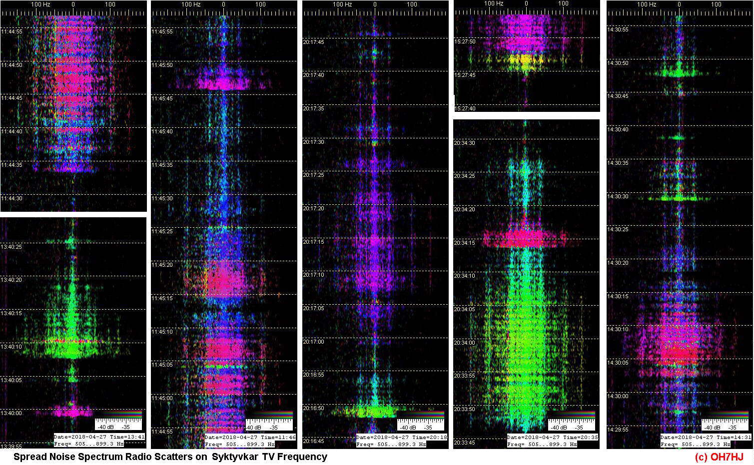
Monipaikkatutka havaitsee meteorikaikuja kaikkina vuorokaudenaikoina, säästä ja valoisuudesta riippumatta. Tutkan nauhoilla tällaiset pitempikestoiset meteorihäntien heijastukset (meteor tail scatter) erottuvat samoin voimakkaampina, kuin tavalliset lyhtykestoiset himmeät meteorivanat. Niiden tuntomerkkinä on tutkan taajuusanalyysinauhoille kohinaisena leviävä hajaspektri. Tällainen kohinaspektri liittyy yleensä sähköstaattisiin purkauksiin kaasussa, joten se antaa vihjeen kirkastuvien ja pitkäkestoisempien meteorivanojen syntytavasta.

On mahdollista, että meteorin iskun yläilmoihin synnyttämä, hetkellisesti sähköä johtava ionisaatiovana sytyttää sähköisesti varautuneiden ionisaatiokerrosten välille sattumalta osuessaan luonnollisen sähkönpurkauksen. Korkean taivaan sähkönpurkaukset tunnetaan yläsalamina tai ionosfäärisalamina. Vähemmän tunnettua on, että meteorit ovat yleensä maankamaraamme nähden sähköisesti varautuneita, aivan samoin kuin niiden lähiympäristön aurinkotuulihiukkaset. Meteorin oma sähköinen varaus auttaa osaltaan ionisoivan meteoriittivanan syntymistä sen osuessa ilmakehäämme.

Meteoriheijastusten ‘hännät’ tutkakuvissa

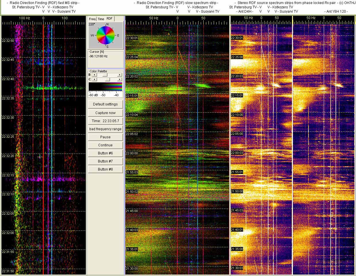
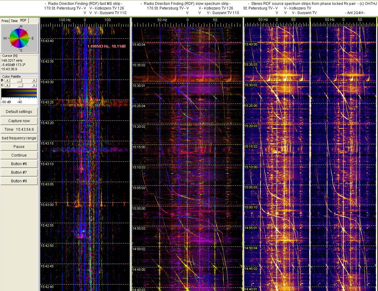
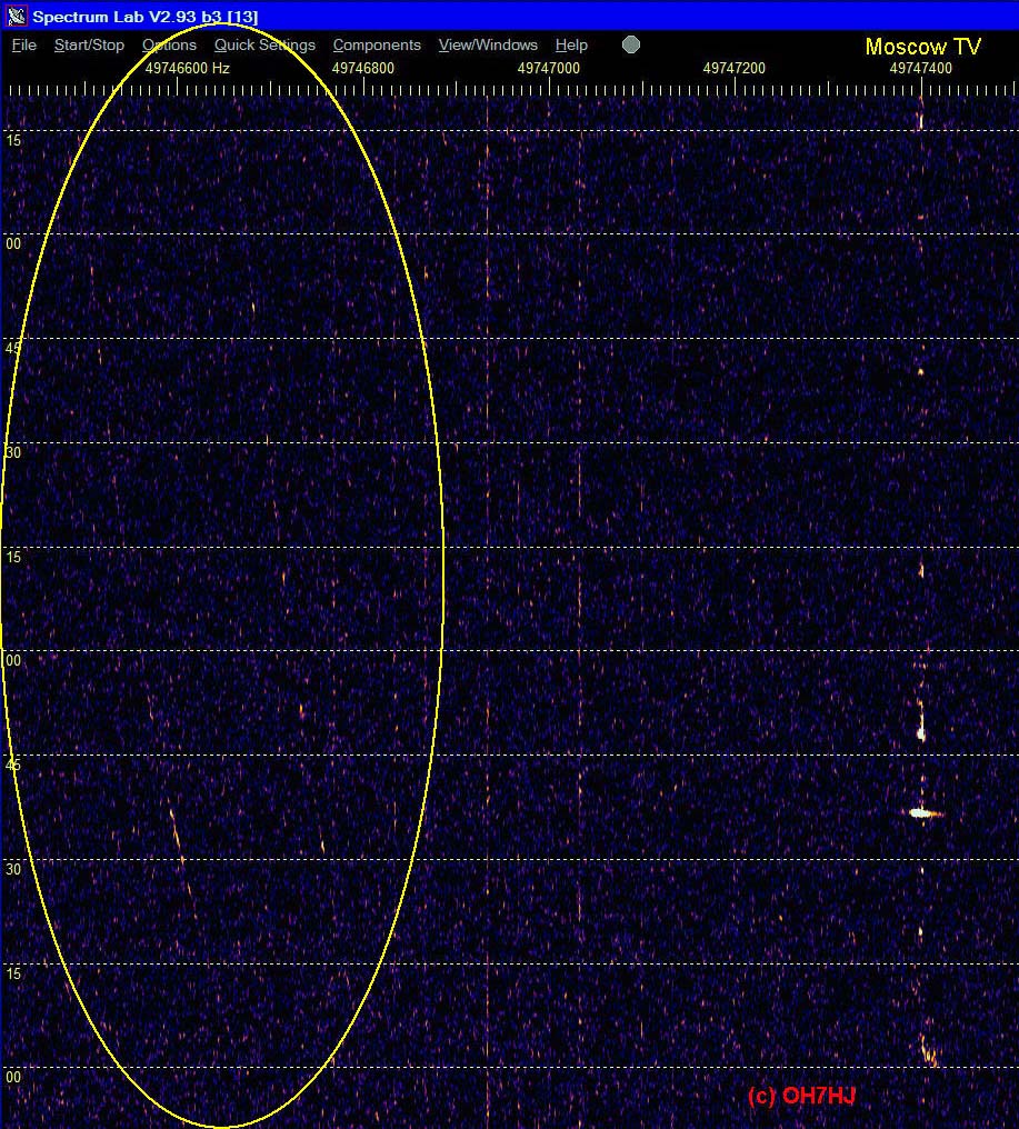
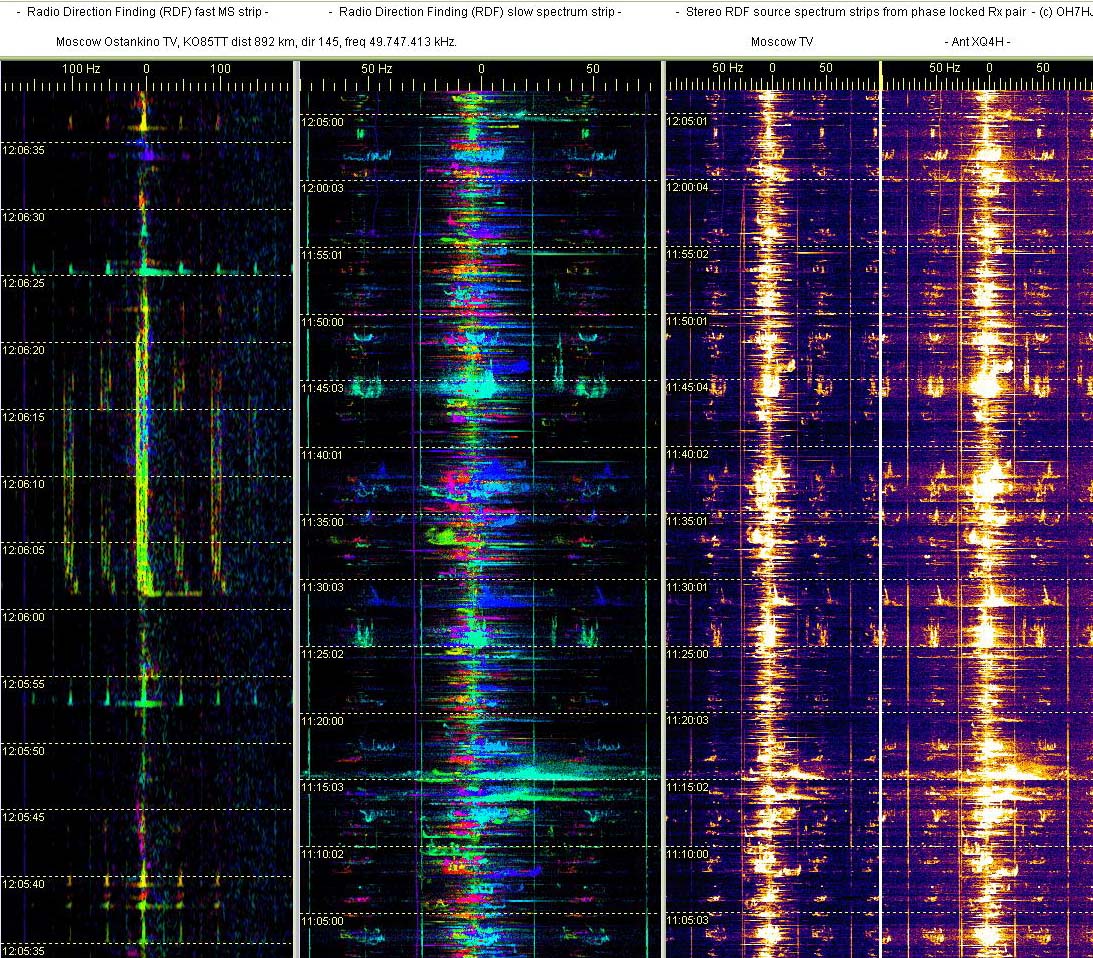
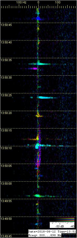
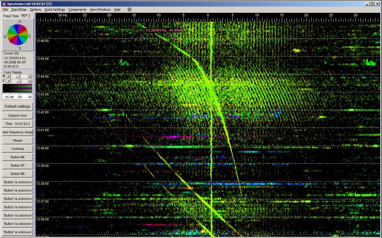
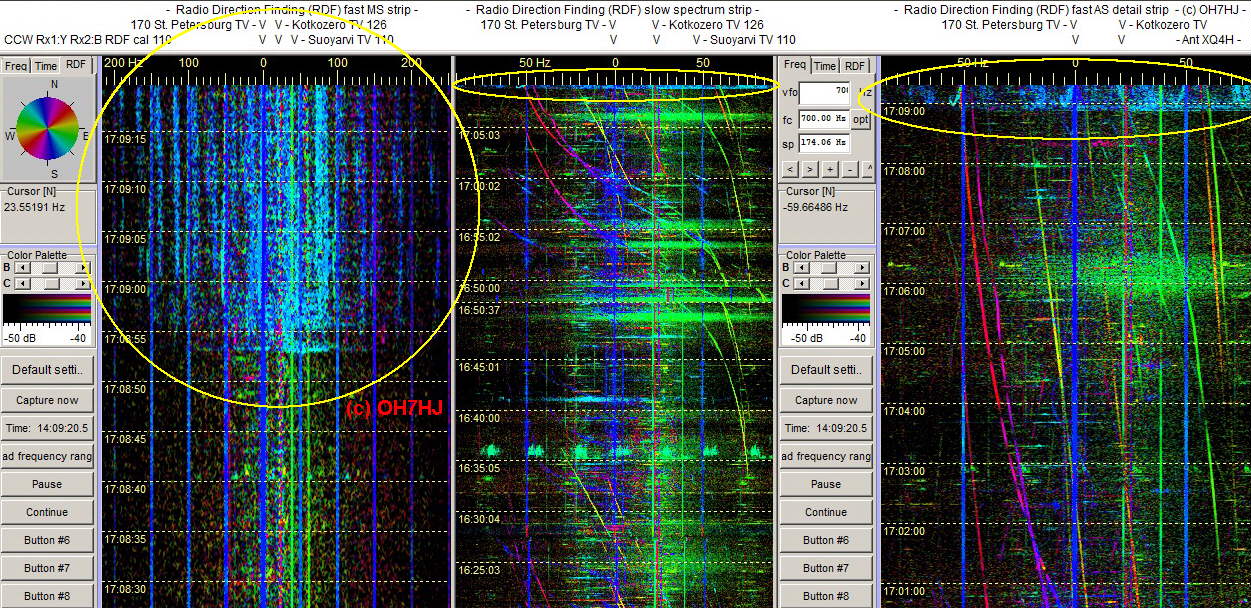
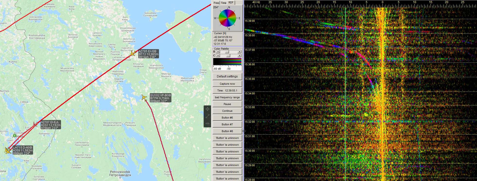
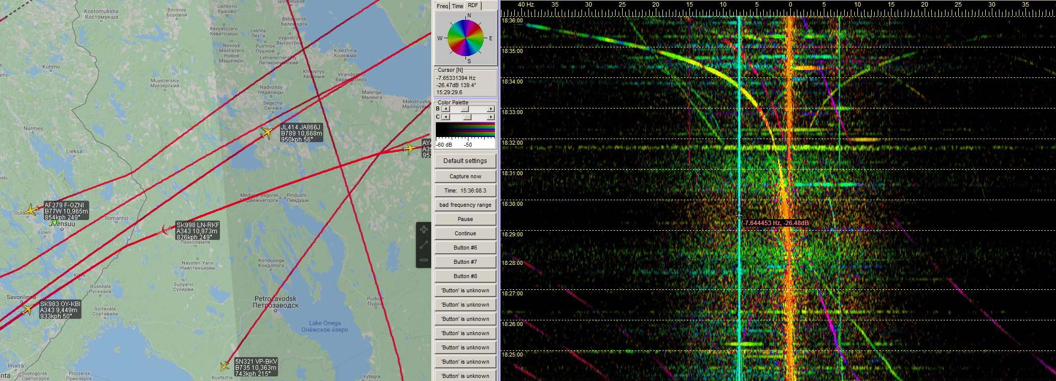
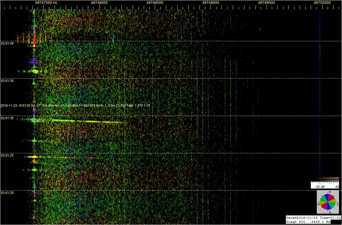
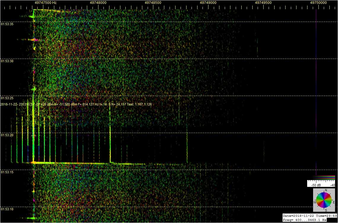
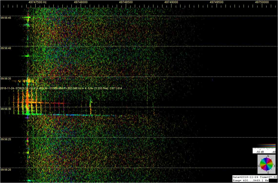
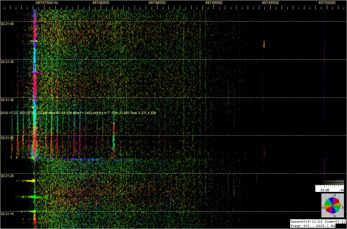
Ensimmäisen liitekuvan eri väriset poikkiviivat ovat eri suunnista kuuluvien nopeiden meteorien ionisaatiovanojen radiodopplereita monipaikkatutkan spektrinauhalle tallentuneina.

Passiivitutkan lähettimenä käytettävän Moskovan TV-kantoaalto näkyy katkonaisena pystysuorana viivana, ja yläsalamien radioheijastukset niiden purkautumiskorkeudesta riippuen eri levyisinä lähes pystysuorina kohinaisten hajaspektrin pätkinä.

Kuva 1: RDF MS Moscow TV - XQ4H in test © OH7HJ - 2018-08-12-1351 - Long and short dopplers.jpg

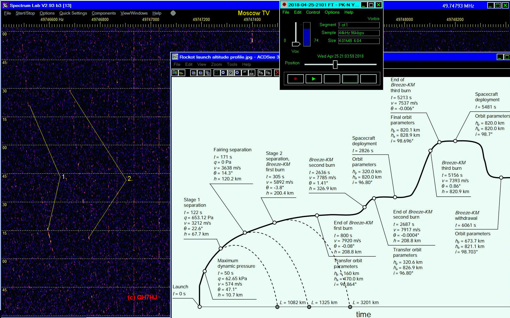
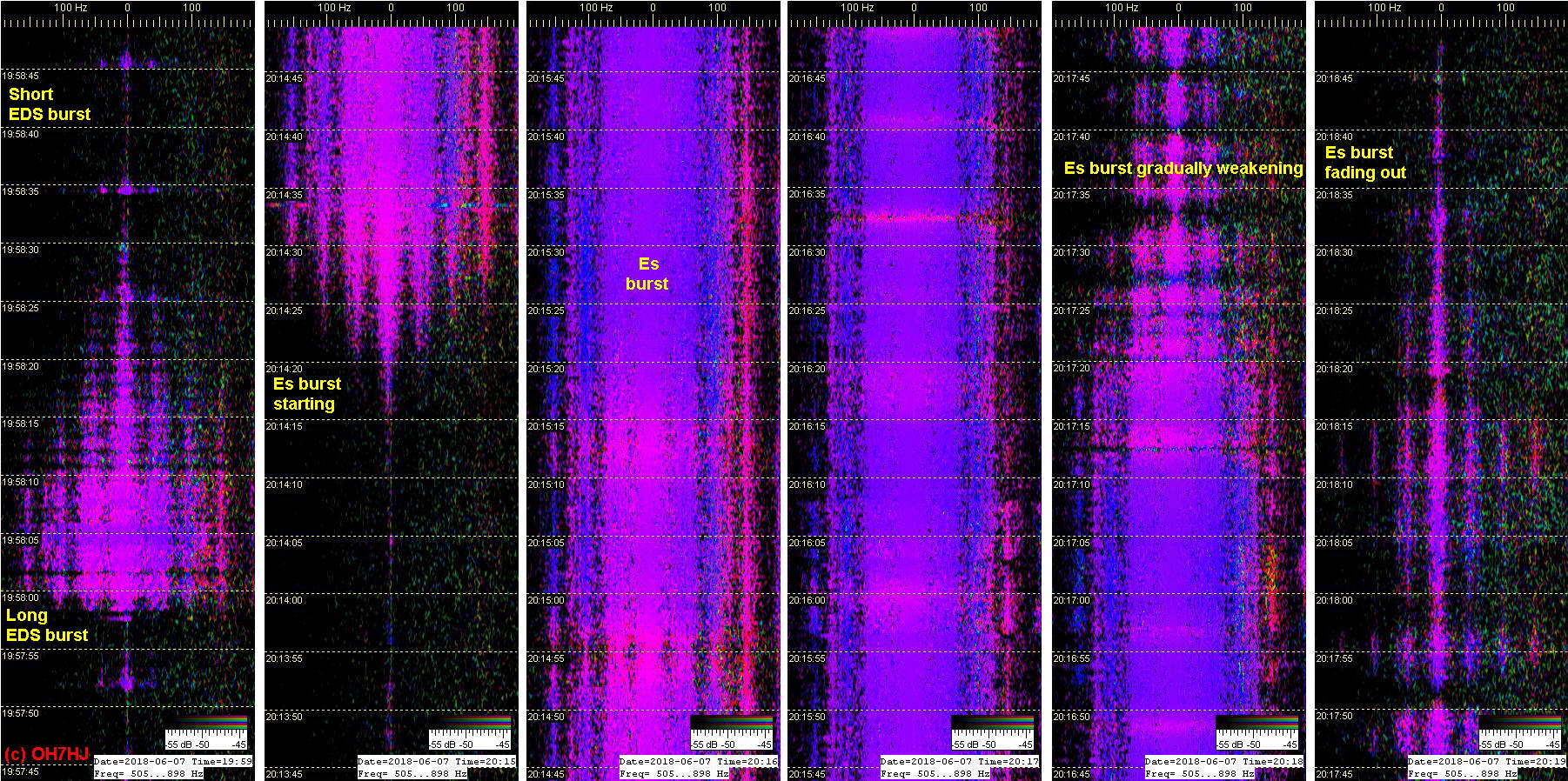
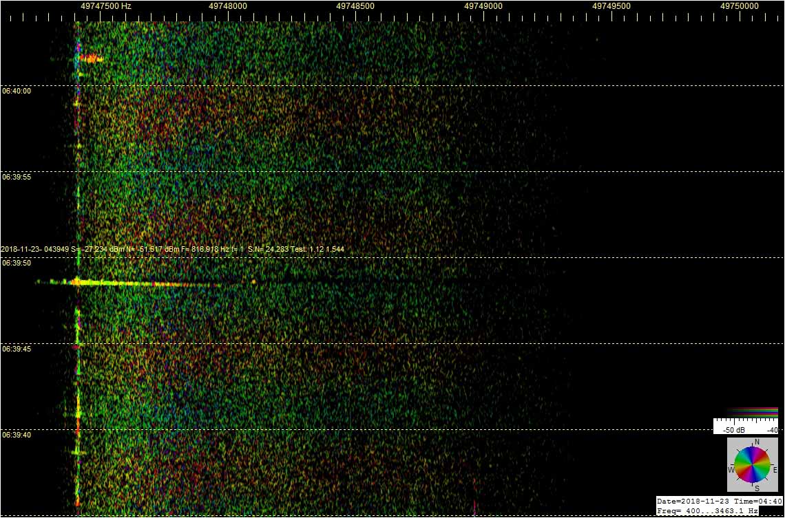
Joskus taivaalta iskevän meteorin ionisoitunut vana osuu niin makean sähköiseen kohtaan yläilmoja, että se laukaisee luonnollisen sähköstaattisen purkauksen, ionosfäärisalaman. Silloin meteorin ionisaatiovananaa pitkin voi leimahtaa salaman purkaussähkön tavallista himmeää tähdenlentoa silmin nähden kirkkaammaksi valaisema valokaari.

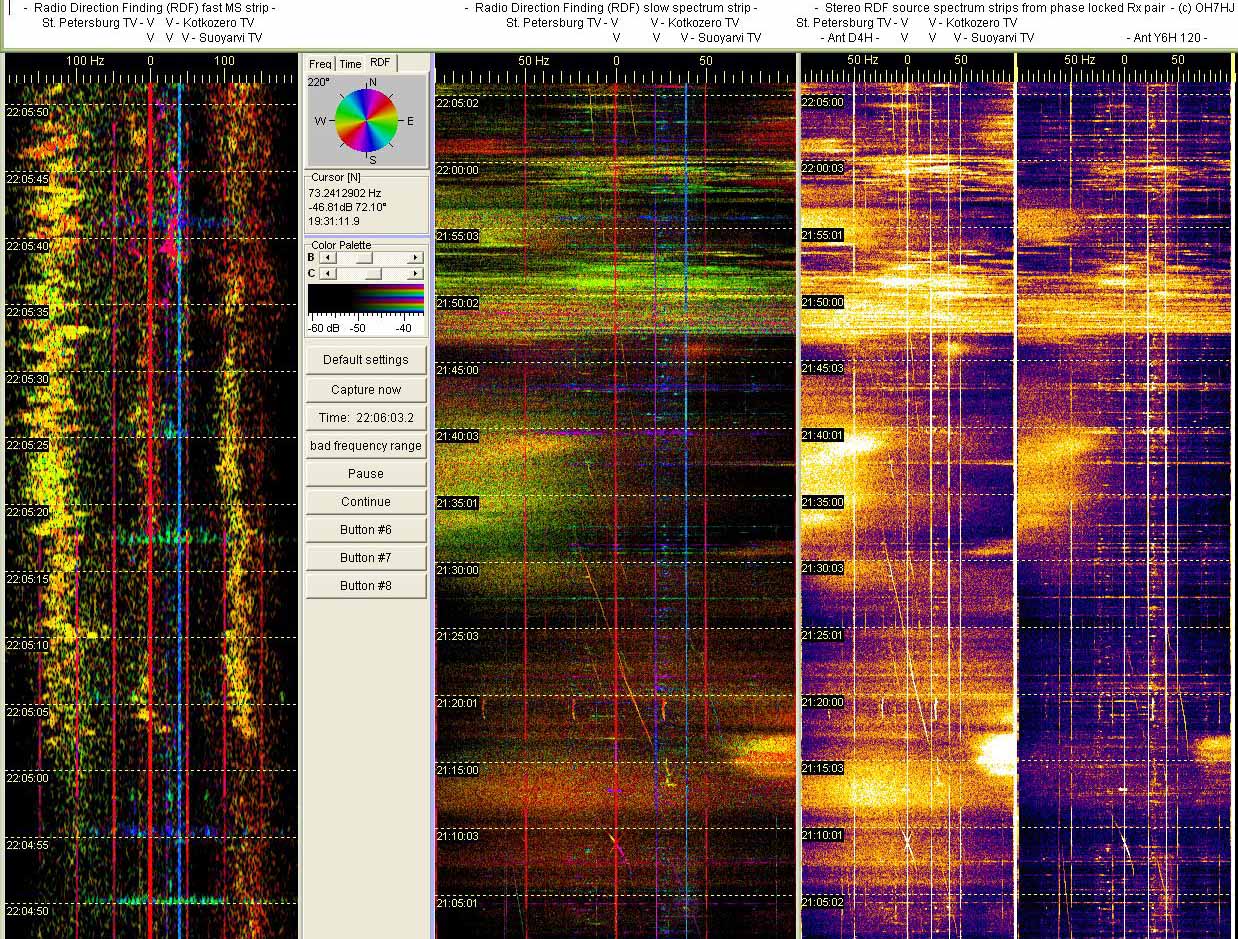
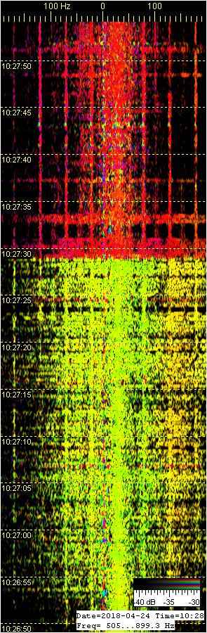
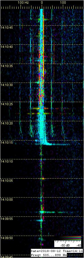
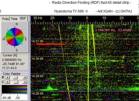
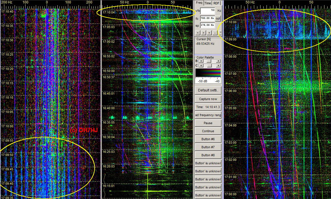
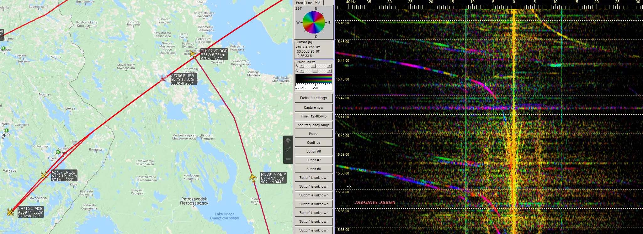
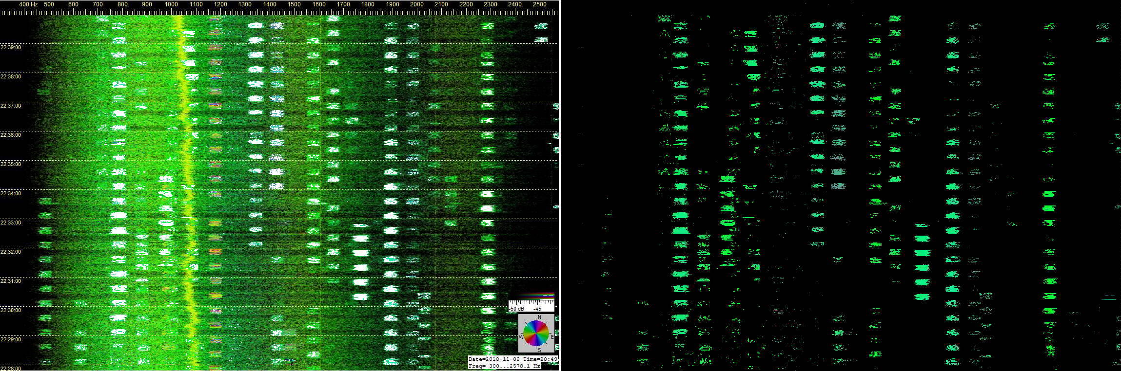
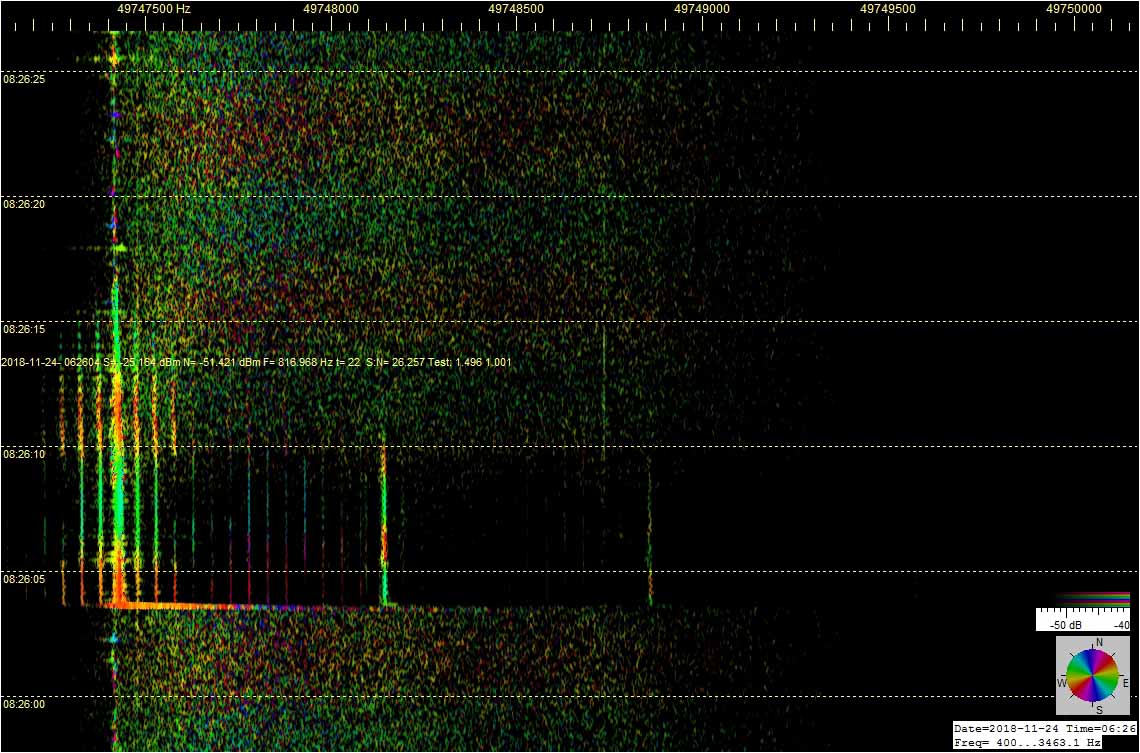
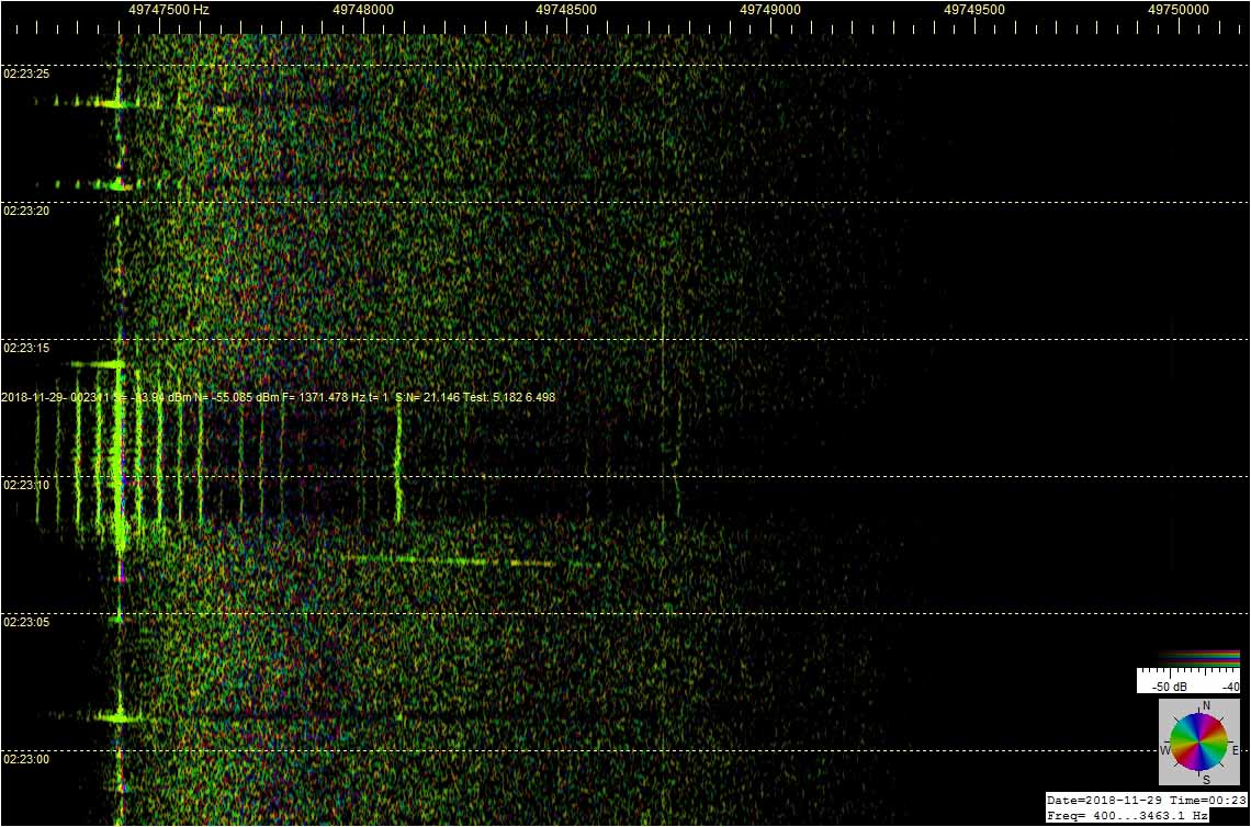
Tutkan nauhalla tällainen meteorin liipaisema sähkönpurkaushäntä erottuu likimain pystysuuntaisena, tavallista ohutta meteorivanaa pulskempana ja pitkäkestoisempana hajaspektrijuovana, kuten on tapahtunut tämän toisen liitekuvan tutkatallenteessa.

Meteorin sähkönpurkaushännän (EDS) rinnalle ilmestyneet raidat ovat purkauksen voimakkaan radioheijastuksen esiin nostamia Moskovan TV-lähetteen 50 Hz sivunauhoja, jotka normaalisti ovat liian heikkoja näkyäkseen tutkan nauhoilla.

Kuva 2: RDF MS Moscow TV - XQ4H in test © OH7HJ - 2018-08-12-1411 - Two long - One with long EDS tail.jpg

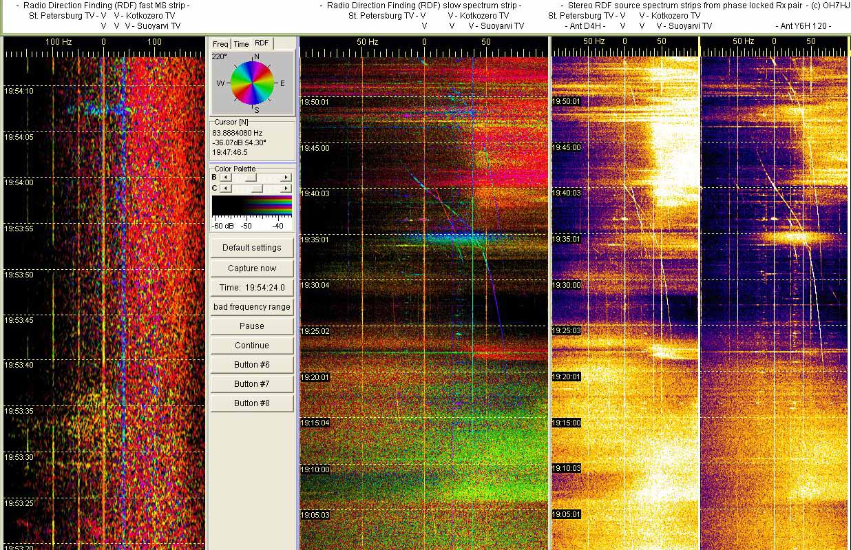
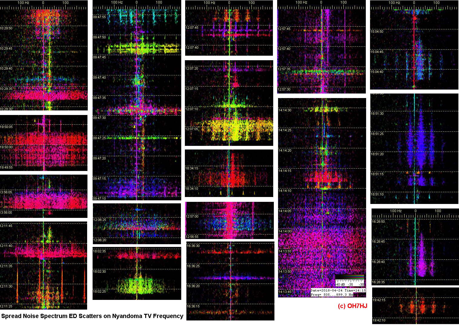
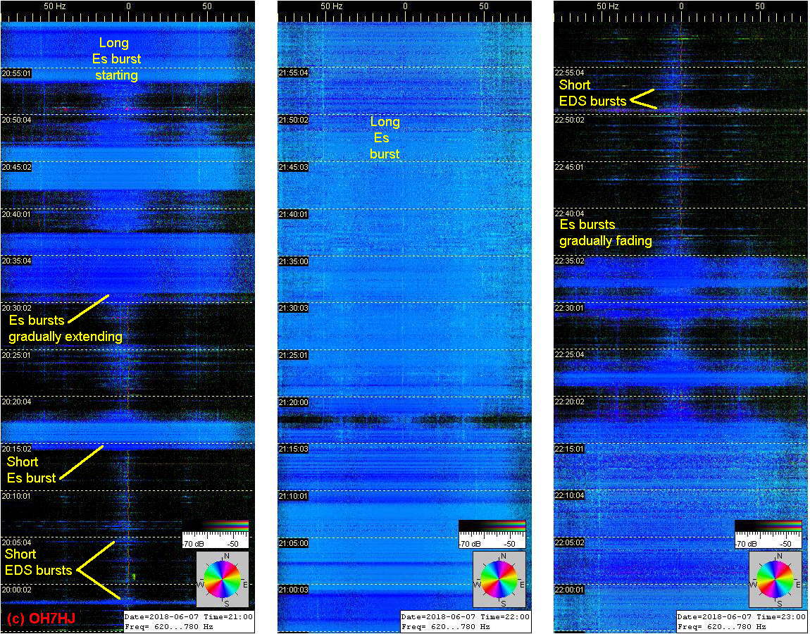
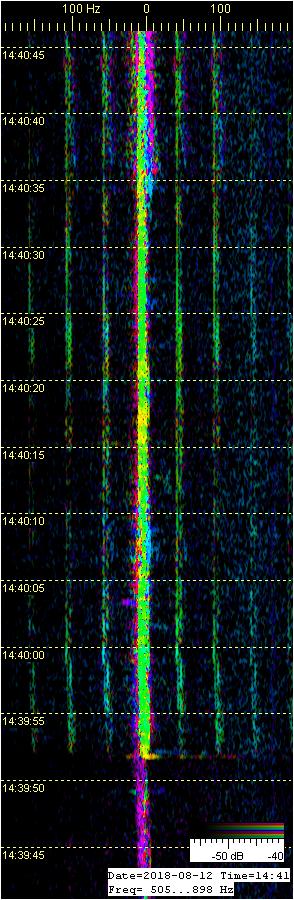
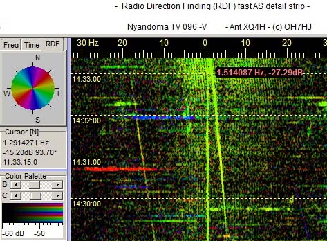
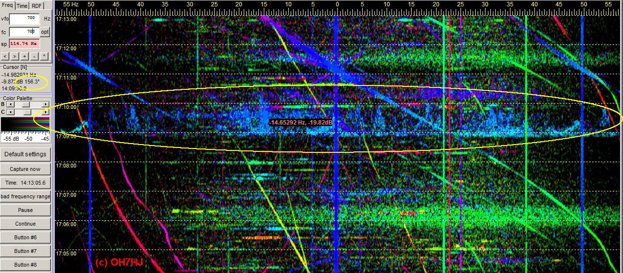
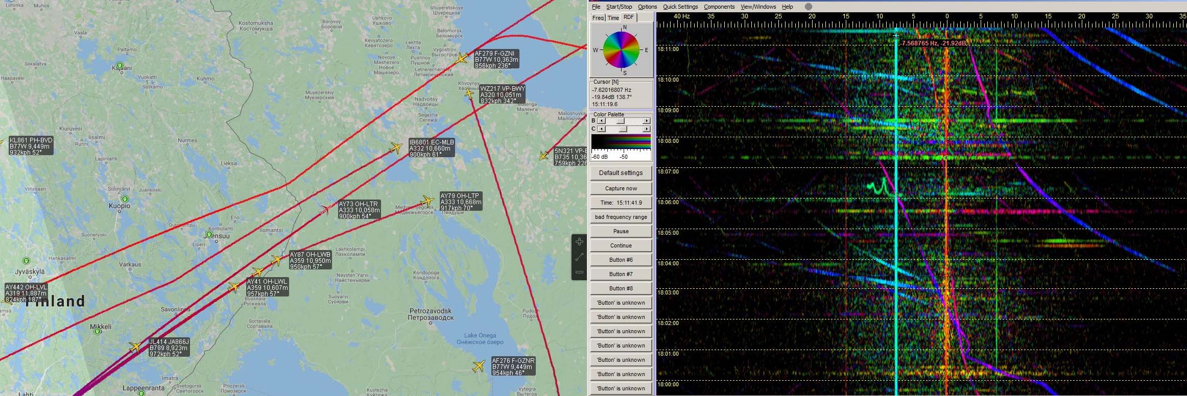
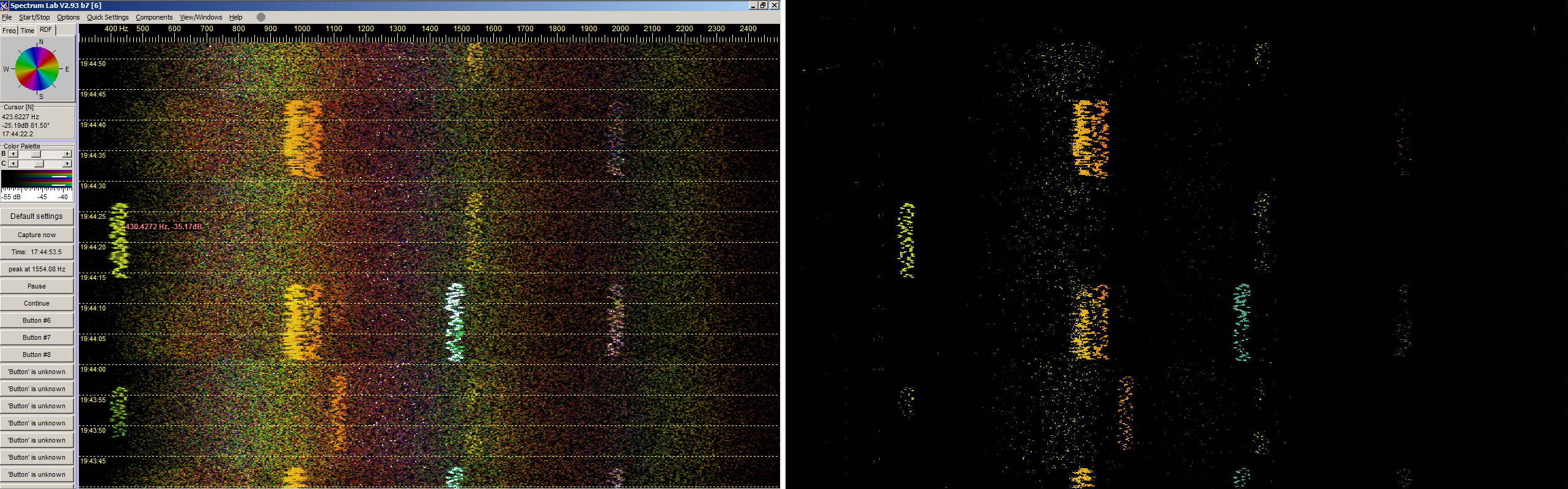
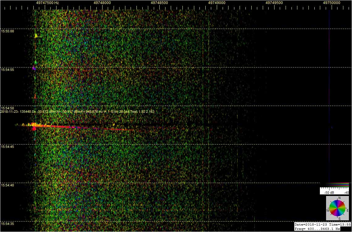
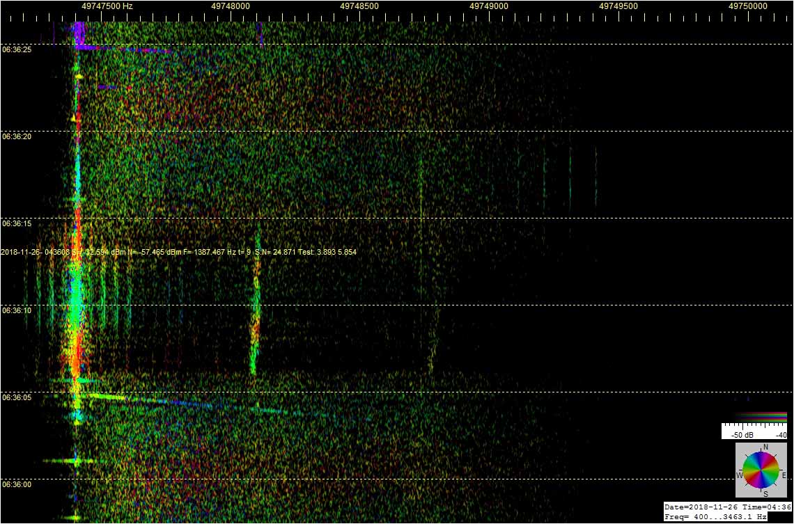
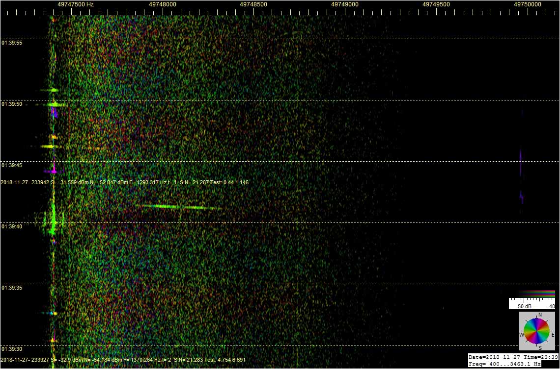
Korkean taivaan luonnonilmiöiden, kuten meteorien ja yläsalamien radioheijastuksia voi monipaikkatutkan nauhoilla näkyä samanaikaisesti useita eri suunnista. Kolmannessa liitekuvassa näkyy keltaisena varsin heikkona dopplerinpätkänä erottuvasta meteorivanasta klo 14:39:52 syttynyt voimakas sähkönpurkausheijastuksen hajaspektri, useine 50 Hz TV-sivunauhaheijastuksineen.

Sinisenä hajaspektrijuovana alhaalla erottuva sähkönpurkausheijastus (Electric Discharge Scatter, EDS) on syttynyt jo aikaisemmin. Värin perusteella se kuuluu eri suunnasta, vaikkakin samalla Moskovan TV:n kantoaaltotaajuudella. Noin klo 14:40:35 näyttää syttyvän kolmas hajaspektripurkaus, jonka tulosuuntaa kuvastava heijastus näkyy myös sinisenä.

Kuva 3: RDF MS Moscow TV - XQ4H in test © OH7HJ - 2018-08-12-1441 - Short MS HE with long EDS tail.jpg

T: - Juha -


Radiosuuntimonauhalla Nyandoman TV-kantis, jonka sivunauhat saavat näyttämään ‘likaiselta’. Sen päällä kulkevat tuntemattomien pulssien muodostamat ‘tikapuut’ poikittaisina askelmina, jotka näkyvät nopeassa radiosuuntimon spektrinauhassa vasemmalla.

Hitaammilla nauhoille oikealle piirtyvät nämä askelmat tiheinä sivunauhoina. Ne näkyvät ikäänkuin ‘höyheninä’ TV-kantiksen ja lentsikkadopplerien ympärillä.

2018-08-31-1348 FT - RDF XQ4H - Nyandoma TV - RDF cal 101 CCW - JL413 doppler from NEE © OH7HJ.jpg

Toisessa kuvassa ovat samat Nyandoman höyhenmäiset TV-sivunauhat suurennettuina. Ne ovat niin vahvat, että näkyvät lentsikkaheijastuksessa, ja seuraavat samansuuntaisina sen doppleria.

2018-08-31-1346 FT - RDF XQ4H - Nyandoma TV - RDF cal 101 CCW - JL413 doppler from NEE detail © OH7HJ.jpg

T: - Juha


A sequence of screenshots about one minute apart of flight IB6888 dopplers on Nyandoma TV carrier and of its RDF bearing from receiver as map degrees.

  1. The RDF display of Spectrum Lab below the color circle points at about 91.4 degrees when mouse cursor is set over the aircraft doppler emerging from up at +3 hz position of the spectrum strip.

2018-08-31-1431 FT - RDF XQ4H - Nyandoma TV - RDF cal 101 CCW - IB6888 from NE © OH7HJ

  1. Reference bearing. Direct ADS-B map view a minute later points with mouse cursor at about 92.5 degrees visible near down right corner of the screenshot.

2018-08-31-1432 FT - IB6888 from NE © OH7HJ

  1. Next minute the flight has advanced at 93.7 degrees by mouse operated Spectrum Lab RDF scale. Its doppler aproaching from left is about to cross the Nyandoma TV carrier visible as upright line a little right of 0 Hz.

2018-08-31-1433 FT - RDF XQ4H - Nyandoma TV - RDF cal 101 CCW - IB6888 from NE © OH7HJ

Natural common high sky spread spectrum radio scatters of faraway TV transmissions sometimes create curious patterns on the spectrum strips. With the Spectrum Lab radio direction finding (RDF) option, we can now approximately tell at which direction each scatter occurs.

Here are curved scatters of TV transmission side bands that resemble hooks. Their peculiar dividing form may be caused by natural ionospheric electrostatic discharges with streamers extending to two or more directions, each streamer creating a branch to its spectrum by doppler effect. These natural scatters could be called ‘doppler forks’ or ‘doppler hooks’ by their appearance.

High Sky ‘Doppler Hook’ Appearing

Here is how one of these spectrum spreading doppler fork curiosities look like on a RDF spectrum with each color indicating SL direction of the signals on the spectrum. At left the emerging scatter is seen on a fast spectrum strip. At right a 10 minute strip is plotting it, and at center it has been captured by a one hour spectrum strip. This doppler hook is a rather long lived one and it has clear spread spectrum branches.

The third pic shows a detail of this doppler hook discharge scatter on a 10 minute spectrum strip. At left is circled the direction of abt 156 degrees that the SL RDF function suggests this scatter is propagating from. Narrow curves are aircraft dopplers changing color while the flight advances. Upright lines are TV carriers and side bands. Very wide ‘noise clouds’ that resemble brief aurora scatters are possibly very high altitude ED scatters.

Rather wide spread specrum and long life time of the scatter like this is supposed to be created by electric discharge scatters (EDS) in high altitudes while ones on lower altitudes seem to be those of shorter life time and they have less wide spread spectrums.

6m 4+4-el Crossed RDF Loop - oh7ab.fi/foorumi/viewtopic.p … 2613#p2598

An example how three aircraft dopplers flying the same route look like on Spectrum Lab Radio Direction Finding (RDF) strip with a crossed 4-el loop array aerial XQ4H on Segezha TV carrier frequency. Their route is close to parallel to Rx - Tx baseline so their dopplers are plotted almost parallel to to the TV carrier for a while.

First pic shows the three dopplers joining TV carrier frequency after the planes pass by Segezha Nadvoitsy TV Tx. Map view is Planefinder.net.

Second screenshots shows their dopplers extracting from the TV carrier as they are bypassing my Rx location. Dividing ‘fork doppler’ is caused by a strong aircraft doppler signal strength close to Rx making intereference ‘mirrors’ and ‘twins’.

Third image illustrates several simultaneous dopplers of planes plotted on the RDF strip. Colors indicate RDF directions calculated by Spectrum Lab from aerial phase shifts.

More example SL RDF dopplers of a rush of aircraft. Setup is same as with previous message. Segezha TV carrier is close to zero Hz marker of the Spectrum Lab RDF strip.

Pic 1: Among usual aircraft scatter dopplers there is a smaller sharp ‘doppler hook’ near the center of the SL strip. This may be created by a natural high sky dividing electric discharge scatter (EDS).

Pic 2: The TV carrier at about -7.5 Hz position of the spectrum strip is Ruskeala TV carrier. Here it has a typical steep rather short aircraft doppler of a plane crossing the Rx-Tx baseline. At the spot marked with cross cursor Spectrum Lab has calculated its RDF direction to be 139.3 degrees from Rx. Ruskeala TV Tx is at abt 140 degrees from my Rx so the RDF calibration seems to be rather good.

Pic 3: Extracting doppler of an aircraft with mirror ‘twins’ caused by strong doppler scatter signal interference. SL RDF suggests 139.4 degrees as direction of Ruskeala TV Tx at mouse cursor point. RDF directions of faraway TV Tx’s vary possibly because multipath effect of surface wave propagation. Above horizon signal source like aircraft doppler RDF directions usually keep rather accurate probably because sky wave propagates directly without need to seek alternative paths like surface wave usually does.

Link to RDF aerial 6m 4+4-el Crossed RDF Loop XQ4H: oh7ab.fi/foorumi/viewtopic.php?f … =200#p2598

Radio Direction Finding (RDF) by two or more aerials allows also many other applications than just direction finding. In principle, any two separate receiving aerials used with a coherent two or multi channel receiver allow assorting signals by their phase shifts. Here are examples of experiments separating desired signals from unwanted noise and interference.

Bare noisy digimode signals are at left with Spectrum Lab RDF screenshots. At right desired signals have been separated by their RDF ‘color’ which indicates signal phase shift. Because there are yet no directional filter software available, I imitated directional filter effect with Picture Publisher software color picking tool.

The qraphical editing tool of this demonstration is of course too ‘hard’ making abrupt signal outlines but the pics should give a rough idea about how direction of wave arrival could be used for selecting desired radio signals. Proper practical signal processing software introducing directional filter would work ‘softer’.

Example signals were spotted and plotted from 160 m band at 1843 kHz LSB with a coherent pair of FT100D receivers. Aerial was the same 6m band XQ4H crossed loop used for my 50 MHz experiments. Despite that the aerial is in this 160 m case built for ‘wrong’ band the crossed loop appears to works on other bands, too, providing necessary phase shift for HF directional filtering effect demonstration.

Regards, - Juha


The experimental multi-static radar listening to 6m band TV carriers streams almost real time USB audio which is quite good for monitoring meteors scatters and their head echo dopplers (MS HE). Here are instructions to set up your Windows home PC to receive and plot this radar sound stream with MS head and tail echoes on your own computer screen.

  1. Load and install Spectrum Lab software by Wolf DL4MH. qsl.net/dl4yhf/spectra1.html

  2. Open two windows of Spectrum Lab.

  3. Load the attached archive file “Remote MS monitoring setup files for Spectrum Lab.rar” and extract them to some folder. This archive contains two Spectrum Lab USR setup files for MS plotting from the remote USB sound stream.

  4. Then load each of these setup files to one of the Spectrum Lab windows from: File > Load Settings from > browse for these two files. “SL1 MS 40mS-line PK-M 49739-49752.USR” configures Spectrum Lab window for low R1 TV band and “SL2 MS 40mS-line PK-M 49755-49762.USR” for high R1 TV band MS plotting.

  5. Download and install some virtual audio cable software you prefer. This software usually installs and works well: vb-audio.com/Cable/

  6. Set this virtual audio cable as Windows default playback device. See the attached screenshot.

  7. Set both Spectrum Lab audio input devices for the virtual audio cable: Options > Audio Settings > Input Device / Stream / Driver > Cable Output (VB Audio). See the illustration attached.

  8. Set your web browser for maanpuolustus.net/pages/tutka/ . Turn its audio volume to maximum. Now the USB sound stream should be flowing to the virtual audio cable. Remark! If your web browser has no volume adjust control visible on the page, try another browser! Internet Explorer usually has a volume control. See the example screenshot below.

Finally apply Spectrum Lab settings. If you got it correct the Spectrum Lab windows should start plotting R1 channel TV from the online streaming radar sound. Then streatch the Spectrum Lab windows proper for you to view them.

Scale with usual OIRT1 channel TV transmitters is on notepad windows above the Spectrum Lab streams that I have put on this thread. Attached are text files of them as archive “Usual R1 TV band transmitters for editing a text file frequency scale © OH7HJ.rar”.

Regards, - Juha OH7HJ
Usual R1 TV band transmitters for editing a text file frequency scale © OH7HJ.rar (785 Bytes)
Remote MS monitoring setup files for Spectrum Lab.rar (19.9 KB)

For automatic capturing of meteor scatter head echoes (MS HE), Timo OH7HMS kindly suggested using a MS capturing script with Spectrum Lab. Knowing that MS HE’s are rather difficult to automatically capture by their signal levels because they are much weaker and less frequent than the common high sky spread spectrum electric discharge scatters (EDS), I was dubious about it. However, there were MS capturing scripts accompanied with Spectrum Lab so I tried one created by Simon Dawes.

Right away there appeared a way to use the frequency range setting of the script to help identify long MS head echoes from among usual strong electric scatters. Strongest MS’s usually draw their head echo doppler lines up to hundreds of Hz above the beacon tx freq. For them, I set the script to watch only those scatters 100 Hz or higher above the 6m powerful Tx of Moscow TV at 49747.41 kHz that gives nice MS HE’s from wide range of sky.

First time trying, Simon’s MS script captured overnight 254 screenshots, of which 101 were left after I removed short HE’s and EDS bursts and missed ones. A lot of 254 screenshots captured by his MS script is a lot easier to check through than thousands of automatic screenshots saved every half minute or so. It means, that Simon’s script works!

Here are some samples of MS HE’s selected from among those automatically captured and labeled by the script. Frequency scale is up and time scale at left with SL time stamps as UTC+2h local and script time stamps as UTC. Spectum strip speed is 40 ms/line. The aerial used was the same 2x4-el crossed horizontal loop XQ4H and receivers the coherent pair of FT100D’s as with my earlier 6m band RDF experiments. Signals on the spectrum screenshots are colored by Spectrum Lab’s radio direction finding (RDF) function by their direction of arrival.

Regards, - Juha OH7HJ

Please click images below to open them.


Color changing MS HE dopplers:

Spectrum Lab RDF function has made colors of these meteor scatter head echo (MS HE) dopplers change by their direction of arrival.

By my first guess, those MS HE dopplers that change their RDF color are likely to be so close to receiving station (Rx) that while they travel on high sky they make a wide enough angle seen from Rx to change their RDF color on spectrum strip.

Here are some examples of these meteor scatter dopplers that change their RDF color while drawing their ionized tails on sky high above us. A reference SL RDF color circle is at right down corner of each MS HE screenhot. Receiving and capturing setup is the same as with previous report.

Regards, - Juha OH7HJ

Please click screenshots below to expand them.


[b]Heavenly Meteor Blues:

Those meteor hits that occur near the Rx-Tx baseline are the strongest because of the baseline forward scatter (BFS) effect. The BFS effect increases scatter signal level about 20 dB or so compared to off-baseline scatters. That is why usually most MS HE dopplers plotted appear to come from the direction of transmitting station (Tx), which in this experiment is the Moscow TV on OIRT1 channel at southeast from receiving station (Rx). [/b]

However, because this 6m band Moscow TV Tx has a very high ERP power it brings visible also some meteor scatters from away from the Rx-Tx baseline. These are colored by the SL RDF function by their direction. Because Rx-Tx baseline to Moscow points at southeast from my Rx, most usual RDF colors for MS are yellow, green and cyan which represent approximate Moscow TV baseline direction on the Spectrum Lab RDF color circle visible on the low right corner of screenshots.

Most usual ones of the rather weak off-baseline meteor scatters visible on these SL strips are red scatters which represent northeast and blue scatters from south direction of the SL RDF color circle. Here are attached some of those evidently from south of my Rx propagating off-baseline blue or RDF color changing partly blue meteor scatter HE dopplers.

Regards, - Juha OH7HJ

Please click screenshots below to expand them.


[b]‘High Flyers’:

Some MS HE dopplers plot interrupted lines on SL spectum strips even if they provide clear strong scatter signal. Because almost all of these dopplers have high dopplers shifts I am using for them a short name of ‘high flyers’. These high dopplers are not very usual but there appear a few of them daily on these 6m band TV Tx carriers. [/b]

The cause of this kind high interrupted doppler may be either meteor trajectory or bistatic scatter geometry or quick velocity or charge loss or meteor falling apart, to guess a few.

As an example of trajectiories, a meteor ‘scratching’ upper atmosphere and escaping again might draw this kind interrupted high doppler. Quick velocity loss might make them decelerate below ionizing speed. Lightweight meteors naturally decelerate quicker than heavy ones.

If ionizing is agitated by meteor electric charge then fast charge loss would cause same. If a meteor is suddenly fragmentized by shock of hitting atmosphere it of course is decelerated quickly, too.

Experiment setup is the same as with my previous meteor RDF reports.

Regards, - Juha OH7HJ

Click screenshots below to expand them.


Jussin OH7TE ystävällisesti Ilkan OH5IY softalla laskemat joulukuun 2018 geminidien meteorisateen saapumissuunnat vuorokaudenajoittain.

  1. päivä joulukuuta klo 23 UTC eteenpäin on sateen maksimi, ja radiantti silloin melko etelässä. Näistä näkyy graafisesti, kuinka korkealla meteorisateen säteilypiste on.

Laskettu lokaattorille KP30HV. Kellonajat näkyvät tiedostonimissä ja ovat UTC. Osa 1.

T: - Juha
GEMINIDS_2018 - 00 UTC.jpg
GEMINIDS_2018 - 09 UTC.jpg
GEMINIDS_2018 - 16 UTC.jpg

Jatkoa edelliseen, kuvat illalle klo 18 ja 23 UTC.

T: - Juha
GEMINIDS_2018 - 18 UTC.jpg
GEMINIDS_2018 - 23 UTC.jpg