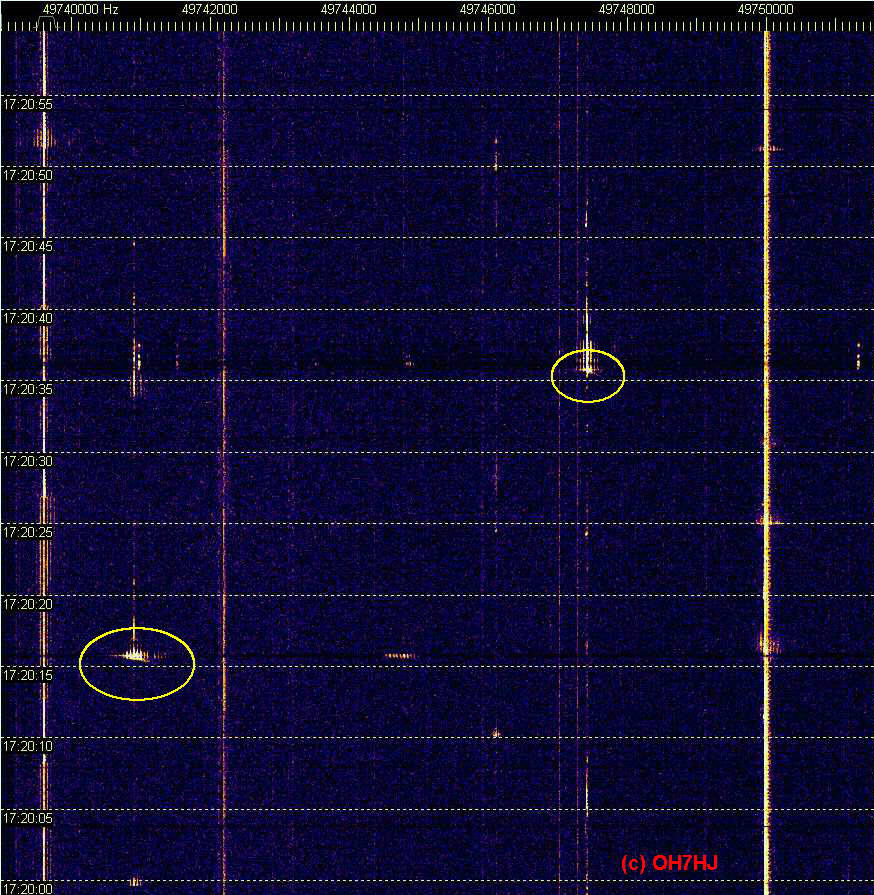
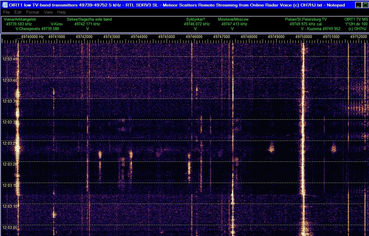
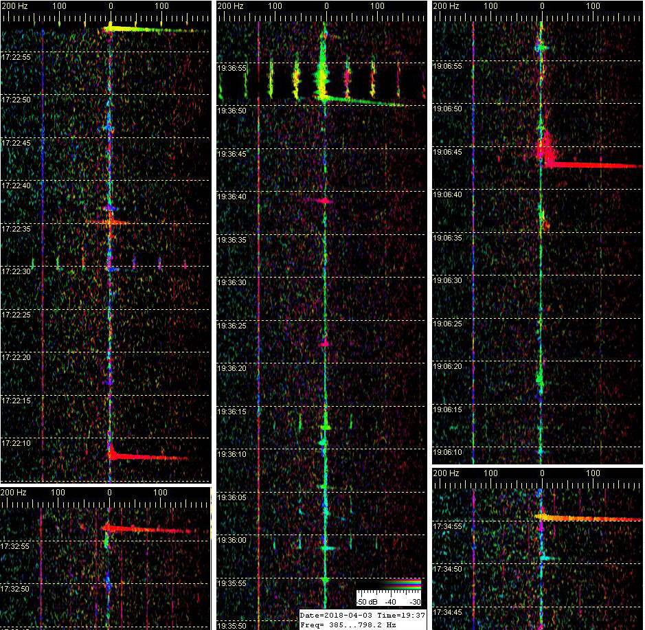
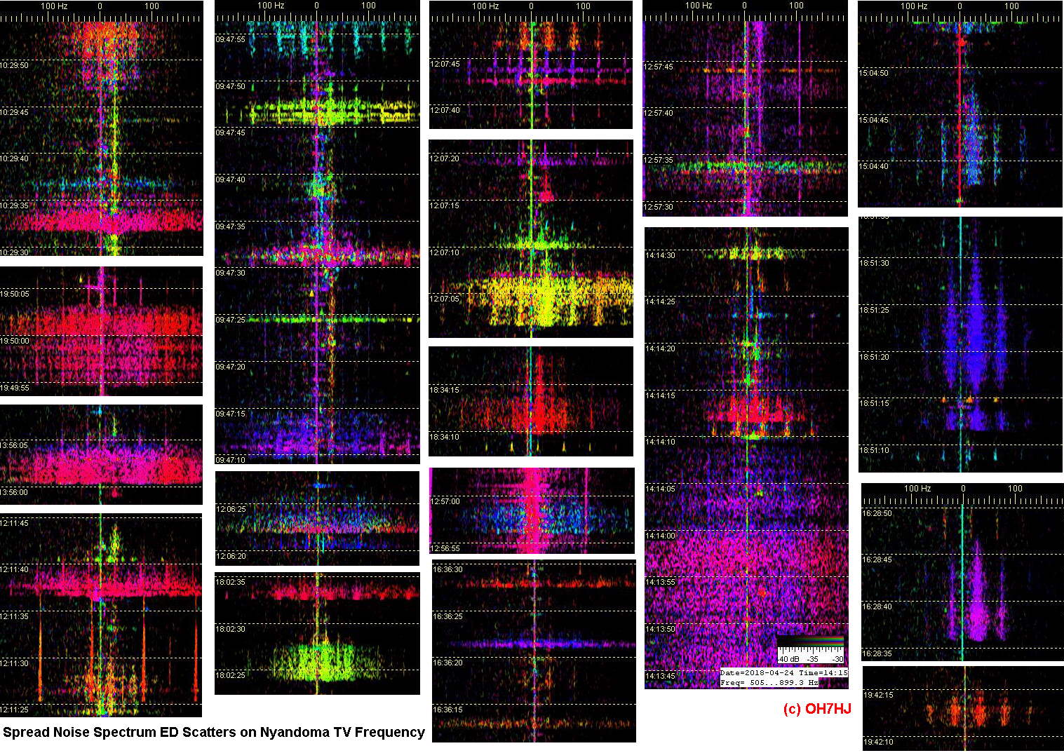
Some meteor scatter head echo dopplers have no ‘tail’. This may be because there happens not to be any high voltage atmospheric electricity to discharge at the point of these meteor high sky strikes. First pic shows MS head echo dopplers without EDS tails.
Most electric discharge scatters (EDS) visible on specrum strils appear to occur without any marks of meteor doppler initiating them. This suggests that either the MS head echo dopplers are too weak to register on receiver strips or the high sky electric discharges are initated spontaneously without help from meteor strikes.
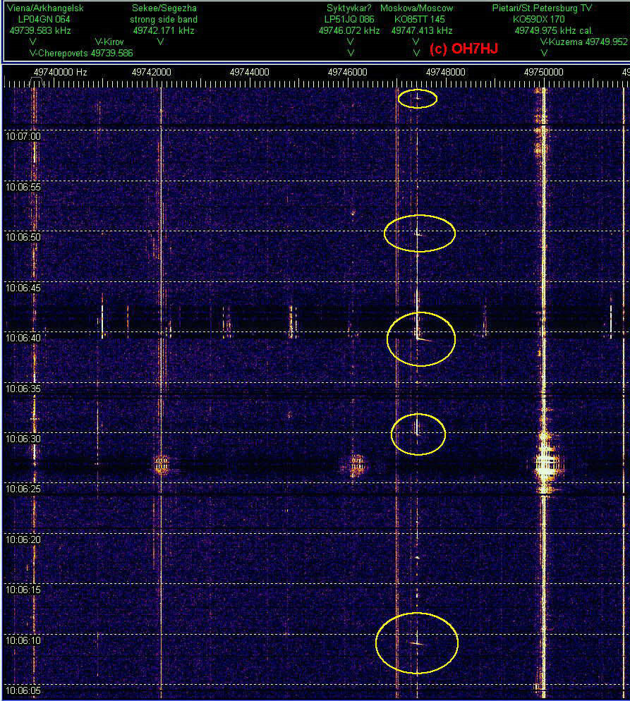
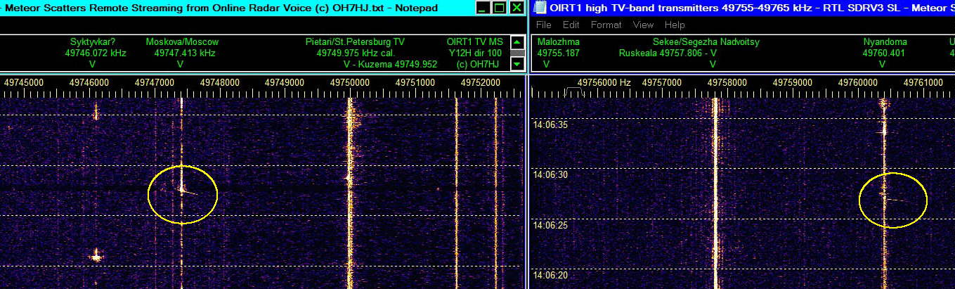
Spectrum strip on second pic has registered three MS head echo dopplers. The longest them is on Moscow TV frequency. Another is on Segezha Nadvoitsy TV. Then there is a weaker one on Moscow TV. These MS hits have very short and weak EDS tails only.
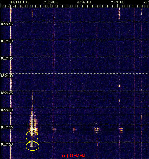
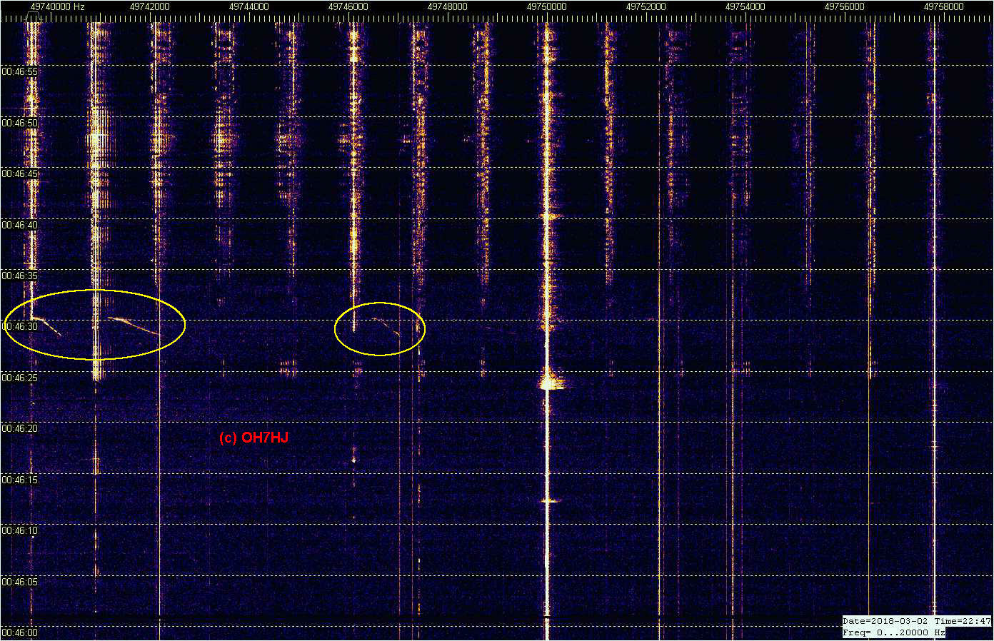
The third screenshot has captured 5 meteor scatter head echo dopplers on Moscow TC frequency. The center one of the dopplers shows stronger than the others. It appears to have initated an EDS ‘tail’ that is strong enough to scatter TV carriers and side bands on wide bandwidth and apparently on many TV transmitters.
Automatic Spectrum Lab periodic screenhots. Two meteor scatter head echo dopplers on Moscow and Kirov TV freqs are initiating immediate ‘tails’ of TV carrier electric discharge scatters and TV 50 Hz side band sets.
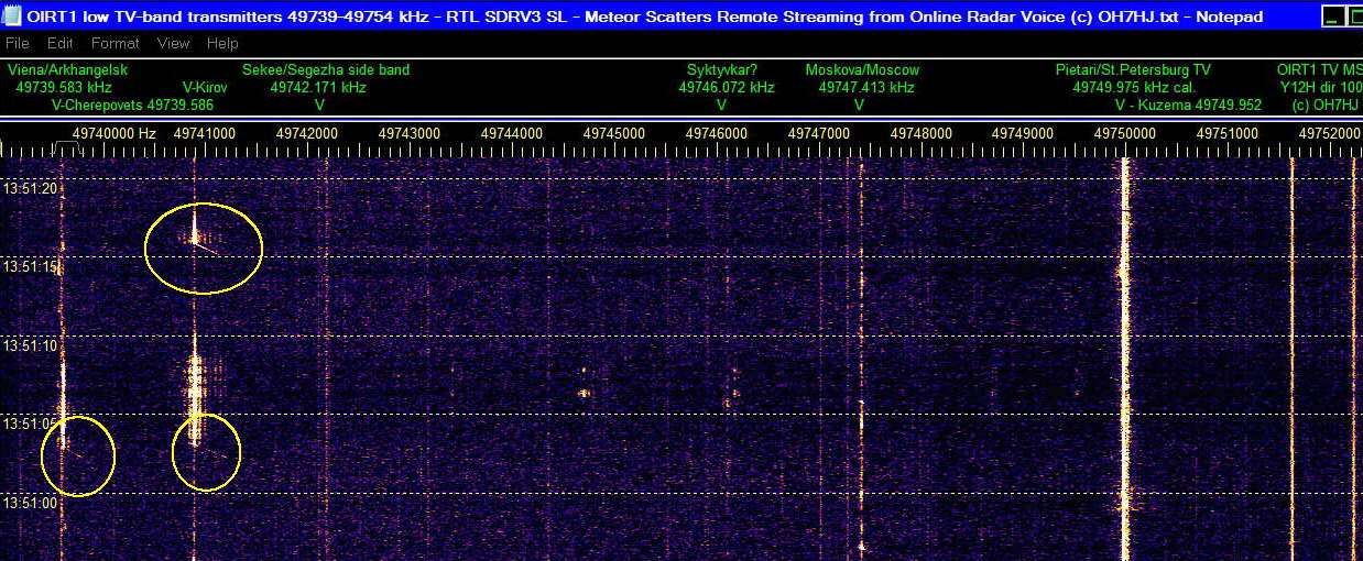
From the second pic a sharp observer can find two sets of faint meteor scatter head echo dopplers scattering sets of TV 50 Hz side bands. The following ED scatters are so strong that they almost hide the triggering meteor scatter head echo dopplers.
Third image show a faint meteor scatter head echo doppler initiating EDS on Kirov TV freq and soon after it a stronger MS head echo doppler on Moscow TV freq producing strong and wide enough EDS tail to momentarily raise receiver AGC and put the strip background black.
I started yesterday observing MS head echoes on R1 TV carriers with setup that experienced MS spotter Esko OH2AUP kindly instructed. With new SDR-V3 wide band multi freq setup I could monitor most of the TV carriers simultaneously to observe MS on them. The aerial is a 2 x 6 -el yagi array for 50 MHz. Receiver is an inexpensive RTL dongle. It seems that I am getting most of the MS head echo dopplers from rather distant TV tx carriers like Moscow, Kirov and Syktyvkar TV. Moscow TV together plot MS head echo dopplers about every 2 … 4 minutes. Closer to me St Petersburg and Segezha Nadvoitsy TV tx’s plot only occasionally, just a few MS head echo dopplers a day. Non-doppler spread spectrum ED scatters are so numerous that they were not counted.
The long baseline meteor doppler observation makes sense when thinking that meteor hits occur very high. It is easier for low horizon aimed TV tx aerial lobes to hit high sky objects from long distance than from close where they are high above the directional patterns of their aerials. Also there is more space to collect greater number of meteor hits between on long rx-tx baseline than between close rx and tx.
Further, high ERP radiated power of TV tx of course brings the usually weak MS head echo dopplers visible easier than on low power beacons. The St Petersburg and Moscow R1 ch TV tx’s have very high ERP power. This should make it practical to copy MS head echo dopplers on their carriers in Central Europe, too. Yagis may be needed for receiving real MS head echo dopplers, however. Meteor EDS tails are much stronger so they are of course visible even with low power receiving aerials.
Remote Listening to MS head Echoes
For those who have no access to 6m band MS receiving aerials I am streaming ‘radar voice’ online as ordinary stereo sound. Spectrum Lab is able to copy remote MS head echo dopplers from this stream through one’s internet browser and virtual audio cable.
I will provide ready Spectrum Lab USR configuration files for MS capturing for those who wish to try. ‘Radar voice’ as online steamed stereo sound: maanpuolustus.net/pages/tutka/
In the future, I have in mind to develope an automatic high sky scatters like MS, Es and ionospheric lightnings locating network of voluntary ham and radio hobbyist receiving home stations. For this, voluntary software developers are needed first. Please let me know if you have coding skills and are interested in joining the effort.
Pics of Strong Meteor Dopplers
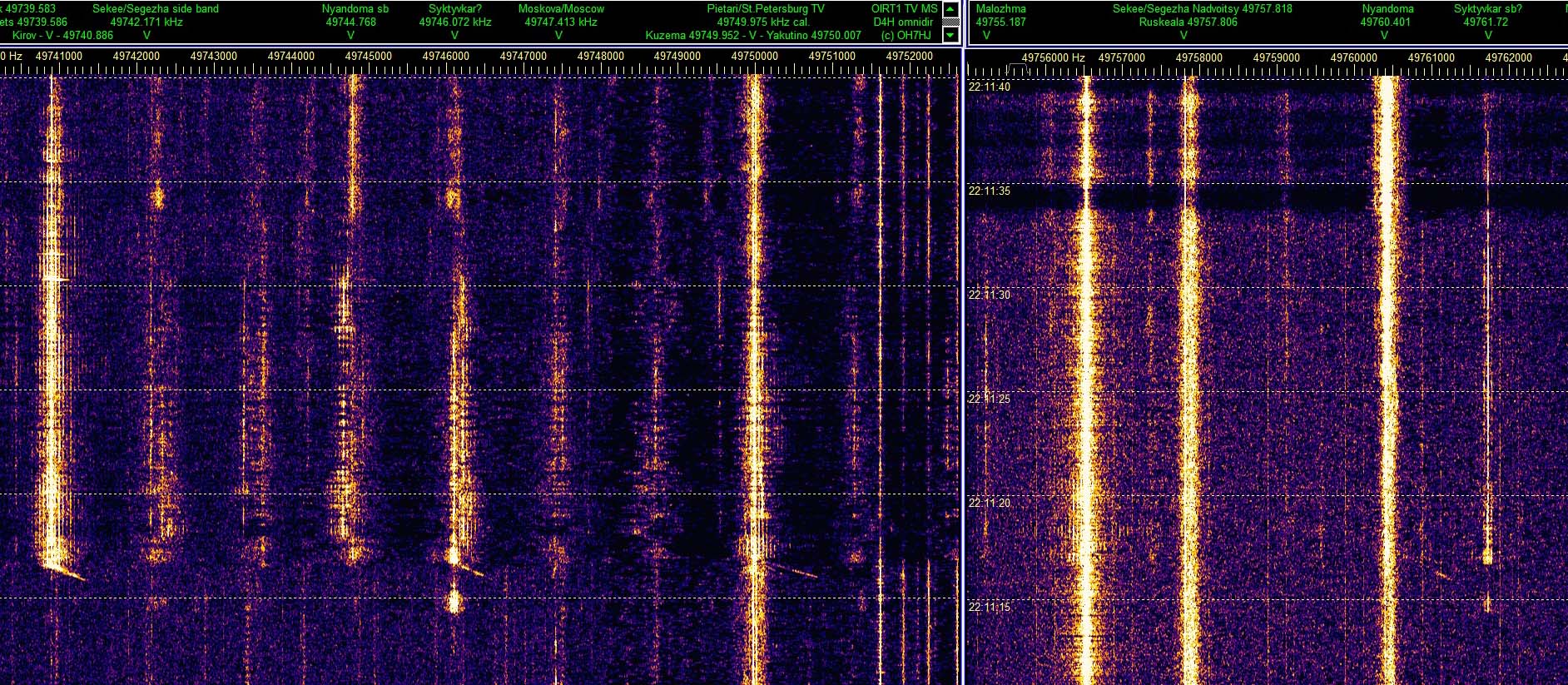
On first pic is a MS head echo doppler strong enough to plot dopplers on three freqs. The strongest is on Moscow TV carrier and the two others symmetrically up and down are possible meteor doppler twins on Moscow TV side bands because they are of same shape as the center one.
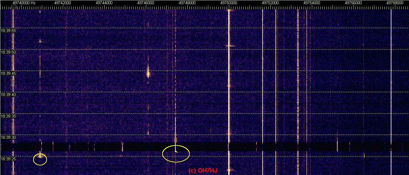
Next pic features a rather long MS head echo doppler on Moscow TV carrier.
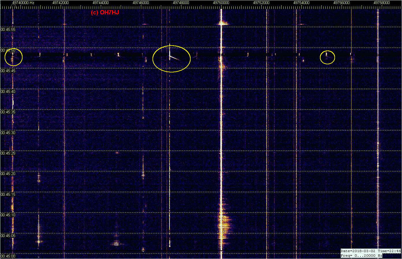
Third image illustrates a long and strong meteor head echo doppler that shows up above at least three TV carrier frequencies: Arkhangelsk/Cherepovets, Kirov and Syktyvkar TV. There appears to be faint fourth doppler above 49748 kHz. These are similarly curved but on different angles so it might be possible to locate this meteor hit by these dopplers.
A couple detail images of meteor scatter (MS) dopplers captured from the online ‘radar voice’. The sound streaming R1 TV channer multistatic radar RTL receiver is now connected to an east pointing 2 x 6 el yagi array. This aerial appears to capture meteor scatter ‘head echo’ dopplers rather well likely because it listens to a large area surrounded by many 6m TV analog transmitters serving as powerful MS beacons.
Small MS dopplers appear every few minutes and fairly long head echo dopplers about a couple times an hour. I have not bothered to count those numerous high sky electric discharge scatters (EDS) occurring every few seconds although some of them are triggered by meteors.
The stereo radar voice contains low R1 band TV carriers starting from 49739 kHz up on left stereo channel and high band R1 TV carriers starting from 49755 kHz up on right stereo channel: maanpuolustus.net/pages/tutka/
Attached images are cropped screenshots from Spectrum Lab (SL) windows registering MS head echo dopplers from online streaming passive multistatic radar stereo voice. These SL windows are set for 1 pixel/FFT bin and 70 mS/line sweep for about one minute meteor scatter strips.
‘Electric Discharge Scatters’ are very usual radio scatters from natural high sky electrostatic discharges like sprites, elves, thunderstorm Es, aurora etc. High altitude discharges ionized air making it conductive enough to scatter radio waves until they rather soon after discharge ceases, cool down and vanish from our receiver strips. So they work quite like little bits of ionosphere except that they have short life time. Sometimes EDS bursts are triggered by atmosphere hitting meteors and are visible on their radio scatter spectrums as their ‘tails’.
High sky discharges appear to be part of global atmospheric electric discharge circuit from high voltage charged solar wind all the way down to ground below our feet. Common ground striking lightnings seem to be the lowest part of the chain of these atmospheric discharges.
Like the thunderstorms, the global daily rate of these natural high atmosphere discharges appears to be constant. This means they occur all the time, although their densest discharge areas appear to move apparently by daily changes of ionosphere.
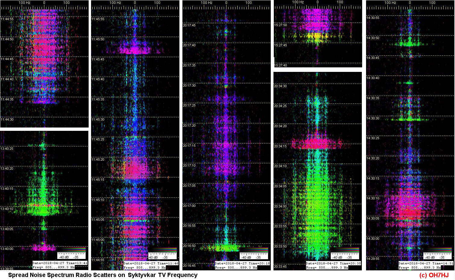
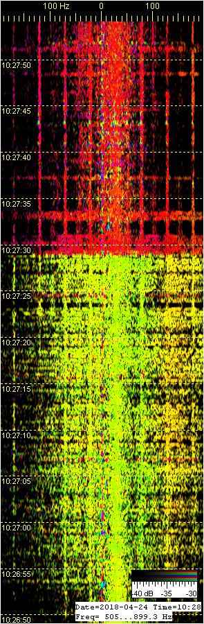
Spread Radio Scatter Spectrum
A distinctive mark of EDS is its spread spectrum of noise that it modulates to radio waves scattering through it. The higher the atmospheric electrostatic discharges occur, the wider they seem to modulate radio wave scatter spectrums and the longer their lifetime is.
Highest easily visible sources of spread spectrum radio scatters are the Northern Lights with their very strong and wide ‘aurora scatter’ spread noise spectrum, familiar to us radio hams as the ‘aurora tone’.
Unlike fast meteor scatter head echo dopplers, the ED scatters usually have little or no doppler shift which means that they are mostly stationary. Sometimes they have small doppler shift which appears to be caused by high altitude winds blowing them. Instead of the sharp doppler of MS head echoes the EDS have their characteristic spread noise spectrum.
MS Triggered ED Scatters
Usually but not always a strong ED radio scatter follows after a MS head echo doppler. This suggests that the downshooting meteor ionized tail initiates along itself an electrostatic discharge between high voltage charged ionospheric layers.
This electric discharge through meteor trail makes a lot stronger and longer lasting radio scatter than the original meteor trail. Their difference is that while meteor doppler has a wide linear doppler shift of high velocity, the EDS tail has little or no doppler shift but instead a spread noise spectrum.
Because the ED scatters usually immediately follow meteor scatters they are commonly but incorrectly believed to be meteor scatters. In reality, they seem to be scatters from natural high altitude electric discharges triggered by meteor downstrike ionized tails.
Spontaneous Atmospheric Electricity Discharges
However, majority of ED scatters show no MS head echo so they appear to discharge spontaneously, possibly by solar wind charging voltage exceeding breakthrough limit to lower layer of ionosphere.
The high atmosphere discharges strike step by step down to the lower layers of ionosphere until the accumulated atmospheric charge finally finds its way down to ground, usually by a charge carrying high vertical wind rotation of a thunderstorm cloud. When a thunderbolt strikes ground the atmospheric electricity circuit is closed.
Natural ED scatters are quite like any ionospheric propagation better visible on lower radio frequencies. That is why there are a lot of them on low VHF bands like the 6m band. They can be heard also on HF when the high background interference allows.
As part of the global atmospheric electricity circuit the high sky ED’s create very many effects observable with radio waves. Old hams were correct when calling the background noise audible through their aerials and receivers as ‘static’, meaning natural electrostatic atmospheric noise (QRN).
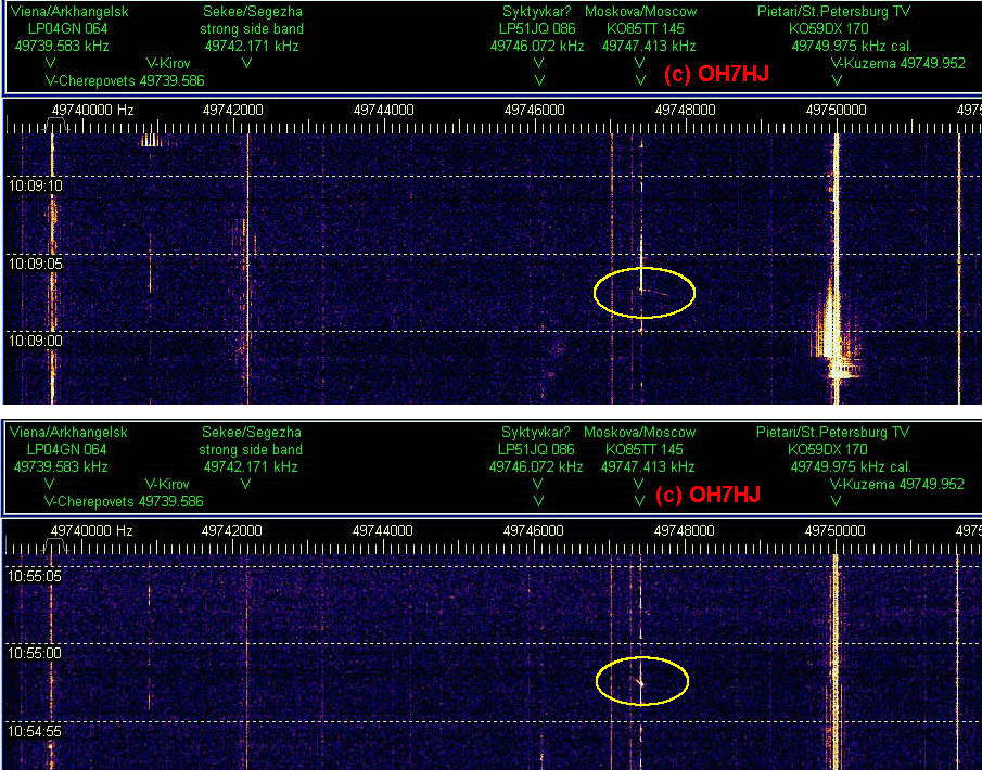
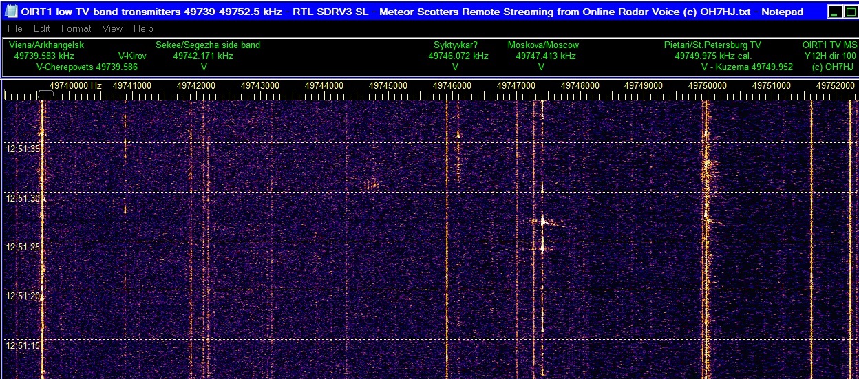
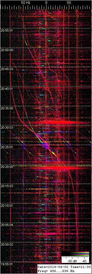
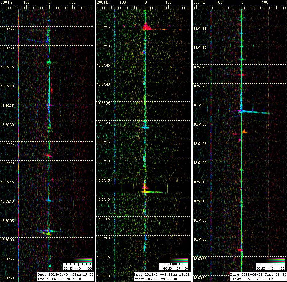
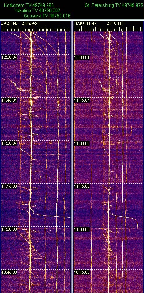
Pic 1: A long meteor scatter (MS) head echo doppler which crosses Moscow TV carrier with abt. 2.5 kHz doppler shift. Visible weaker on St Petersburg and Arkhangelsk/Cherepovets TV carrier freqs, too. The EDS tail appears have ignited before the MS doppler appears. This suggests that this EDS burst may have initiated spontaneusly or by another MS hit and occurs only coincidentally over this unusually long MS doppler.
Pic 2: MS dopplers are usually short and rather rare on St Petersburg TV carrier, maybe either because it is so close and aerial beam is aimed so low that there is not much high meteors that hit between it and rx and low enough. However, here is one that apparently has been large enough to reach down into St Petersburg Tx beam. Strength and length of the MS head echo suggests that it has hit somewhere rather close to SE Finland. The EDS tail of this meteor hit is so strong that it raises TV side bands clearly visible.
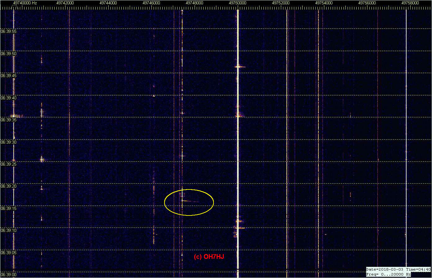
Pic 3: A simultaneous MS doppler on St Petersburg and Moscow TV freqs. This one has a very weak EDS tail only.
Pics are cropped from the original set of two Spectrum Lab windows to fit the message thread. Captured from the online radar voice stream from RTL rx with 6-over-6 6m H-yagi array (Y12H) aerial pointing dir 100 degrees. Time labels are Finnish local UTC + 2h. Frequency scale is at top as Hz with usual R1 channel TV Tx’s marked. Please click pics to open and see dopplers.
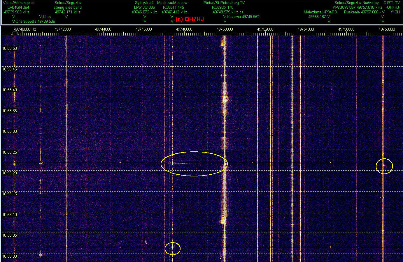
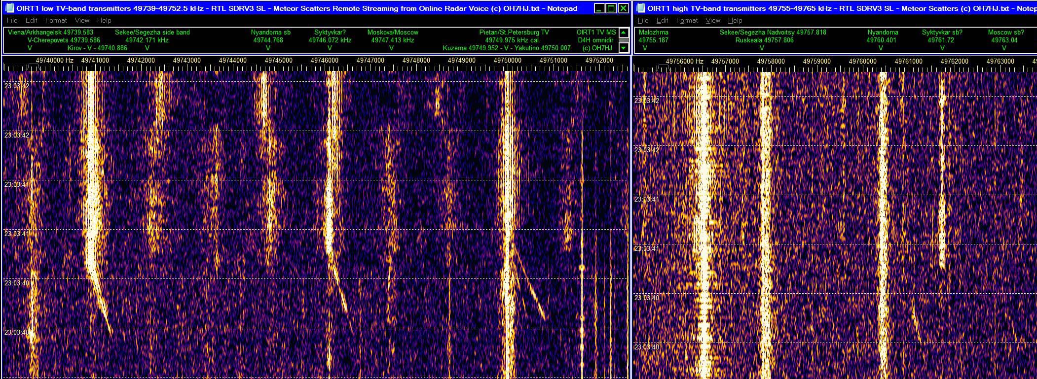
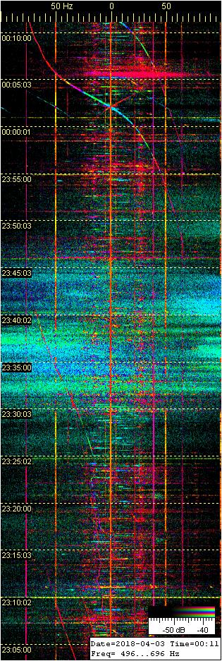
Meteor scatter (MS) head echo (HE) doppler appears on up to six 6m band R1 ch TV Tx freqs simultaneously. There was aurora which made some of these TV carriers ‘fat’ by the aurora typical electric discharge scatter spread noise spectrum.
On St. Petersburg TV carrier there is a faint fifth MS HE doppler right below the strong one. The weak MS doppler is probably caused by meteor trail crossing of one of the small Lake Ladoga area TV Tx carriers like Kotkozero or Suoyarvi. There are also traces of sixth MS doppler on Nyandoma TV freq.
Concluding dy bistatic radar baseline forward scatter effect on Tx’s the likely directions of these MS doppler crossings a possible meteor hit area might be East Finland or Carelia. Meteor scatters like these on multiple Tx frequencies simultaneously could be tracked and located if there were software available for it.
Known TV Tx’s are listed in the scale on top of of each screenshot. Frequency scale is in Hz. Time stamps are FT local plus online streaming delay of abt 10 … 20 s. Recording playback time stamps are arbitrary. Captured and cropped from the online 6m MS multistatic radar voice stream on: maanpuolustus.net/pages/tutka/
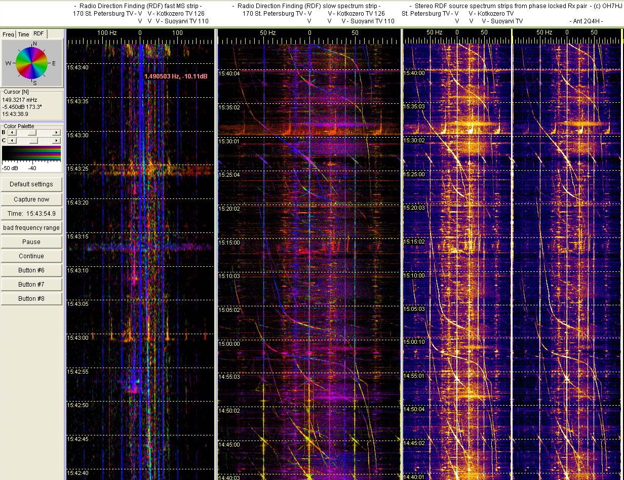
50 MHz TV-bandin radiopeilauskokeiluja Spectrum Labin RDF-modella. Ekan liitekuvan oikeanpuoleisissa SL-nauhoissa on kummassakin sama Pietarin jakso, mutta eri antenneista, kuunneltuina koherentiksi muokatun hamssivastaanotinparin kautta. Vasemmanpuoleisella nauhalla näkyy näiden kahden antennin vaihesiirto, joka vastaa kutakin väriä. Eli aallon tulosuunta.
Nauhalta näkyy, että RDF antaa suuntiman periaatteessa spektrin jokaiselle pisteelle. Kun hiirellä osoittaa nauhaa, viereiselle ruudulle ilmestyy spektripisteen taajuuden, ajan ja sinkunvoimakkuuden lisäksi sen suuntima asteina. Pietarin, Kotkozeron ja Suojärven lähetinten tunnettuja suuntia voi käyttää suuntimien kalibroimiseen. Tällainen kahden antennin suuntimo antaa tietenkin myös peilisuuntia.
Ensimmäisessä oheiskuvassa lentsikkadopplereiden värit liukuvat suuntiman muuttuessa koneiden lentäessä kuunteluasemani ohi. Lyhytkestoiset luonnonskatterit esiintyvät eri väreissä, niiden aallon saapumissuunnan mukaan. Kolmannen liitekuvan aurorapurskeessa näkyy revontuliskatterin tulosuunnan vaihtelu aurorakohinan värin vaihteluna.
Tästä keskeneräisestäkin koejärjestelystä selvisi, että softa ja vastarien yhdistäminen koherentiksi eli samanvaiheiseksi pariksi näyttävät toimivan. Tämä järjestely ei ole vielä valmis ihan ‘oikeiden’ suuntimien ottamiseen. Tekee vielä liikaa suuntien monikertoja, koska tilapäisantennit ovat keskenään erilaiset, ja liian kaukana toisistaan.
Kunnollisen RDF-antenniparin rakentamista on siis tiedossa, kunhan lumet sallivat. Sitten pitäisi päästä harjoittelemaan TV-lähetinten, meteorien, yläsalamien ym. taivasaaltojen peilausta. Jos pelittää, niin on paljon vaivattomampi ja nopeampi menetelmä suuntia, kuin numeerisesti laskien usean eri noden dopplereista. Toinenkin aseman tietenkin tarvitaan ristisuuntimien ottamista varten.
Started experimenting with radio direction finding (RDF) of MS head echo dopplers and other high sky scatters, inspired by inexpensive radio interferometry setup introduced by PE1ITR.
Only software that I know is available for us hams with interferometry RDF option is the familiar Spectrum Lab. So I joined a pair of FT100 ham receivers together to create a coherent pair of Rx’s needed for a simple two aerial interferometer.
These first pics show examples of 6m band MS HE’s in different colors. Each color is for phase shift between these two signals for separate aerials. In practise, for direction of wave arrival. Two aerial interferometer of course gives mirror directions, too.
Although this experimental arrangement is incomplete by its temporary unpaired aerials that are too far from each other, it seems to confirm that both the SL RDF software and the homebrew coherent rx modification appears to work.
Later when able to build proper RDF pair of aerials - I hope - will be able to provide reliable directions of arrival for natural high sky scatters like these MS and EDS. Still further, will of course need another RDF node for crosslocating these scatters.
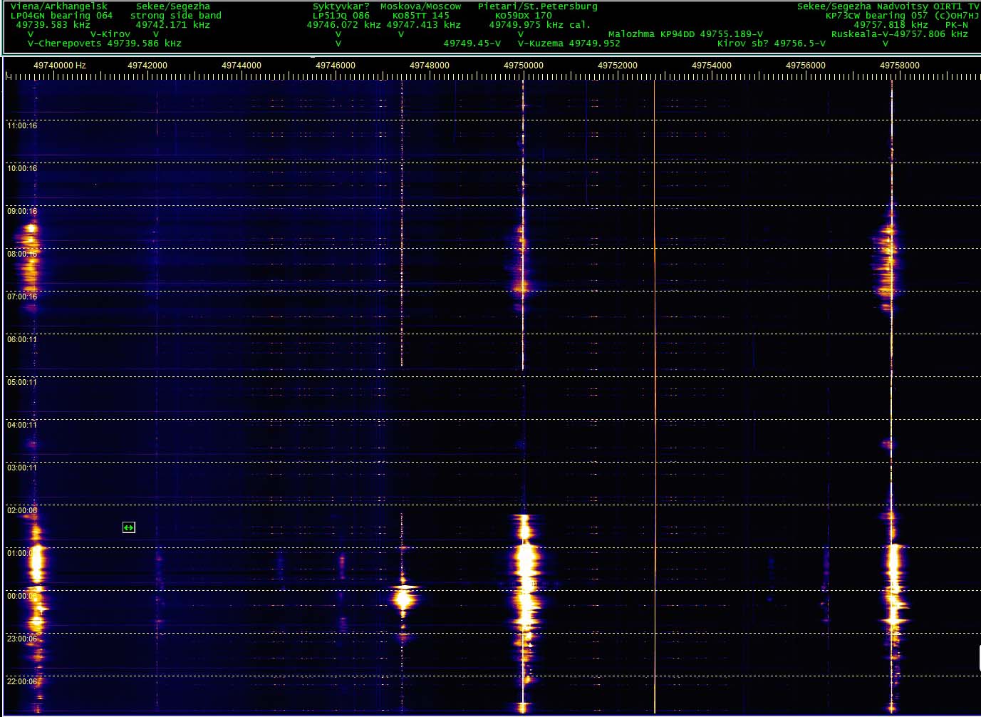
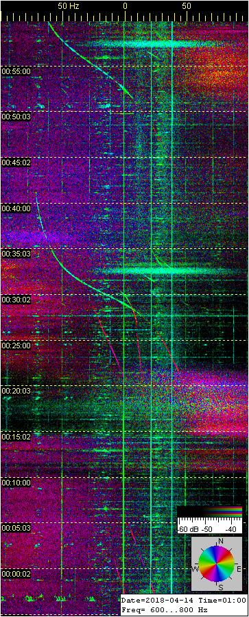
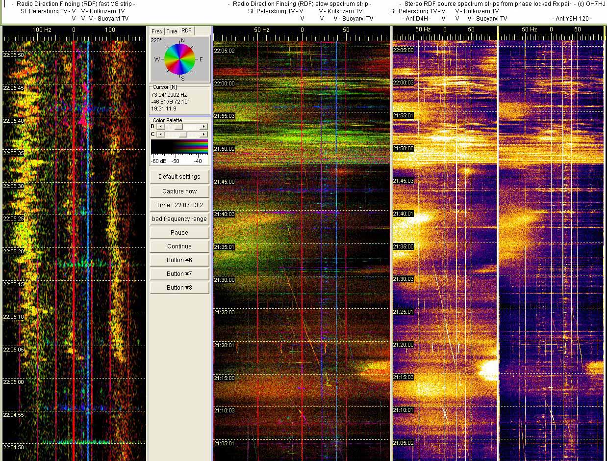
Eilissäöiset revontuliheijastukset näkyvät ‘pumpulisina’ kohinajaksoina puoliltaöin ja aamulla tässä tutkanauhalla parhaiten Vienan, Pietarin ja Sekeen TV-lähetinten taajuuksilla. Myös eteläisempi Moskovan TV on näkynyt auroraheijastuksena keskiyön aikaan, mikä yleensä merkitsee revontulirintaman laajentuneen tuohon aikaan pisimmälle etelän suuntaan.
Revontulten vaiheita voi seurata lähes livenä puolen tunnin välein päivittyviltä monipaikkatutkan online-demosivun nauhoilta, joista ylempi näyttää TV-asemien kantoaaltotaajuuksia suurennettuina ‘detaljikuvina’, ja alempi ‘revontulitutkakuva’ leveänä spektrinä: maanpuolustus.net/pages/tutka/
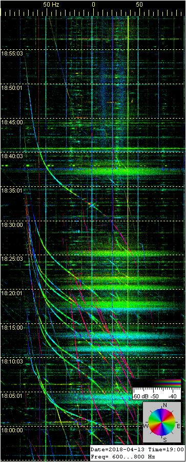
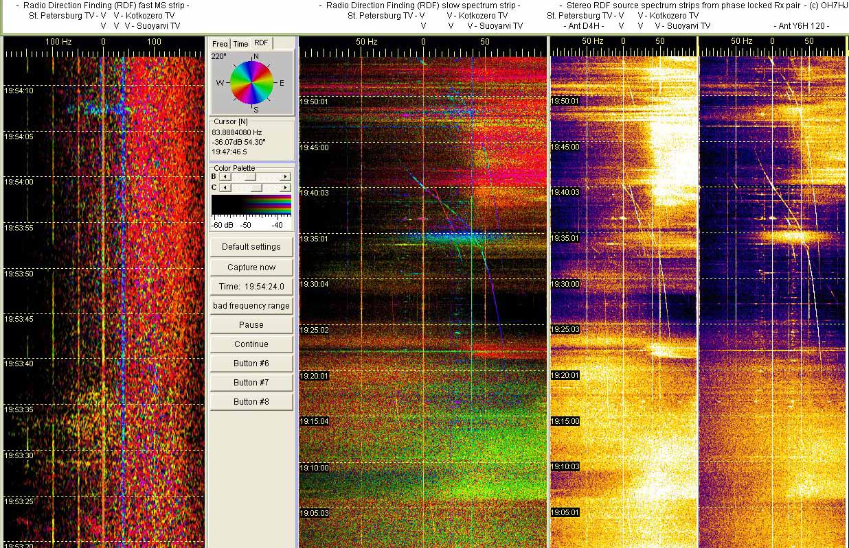
Aurora Borealis or Northern Lights are sometimes preceded by radio scatters of something that appear like short aurora flares. These ‘aurora precursors’ appear otherways quite like usual long duration aurora scatter on these passive radar strips except that they last only about a minute.
The high sky events that create these 50 MHz rather short radio scatters are not yet known but by the wide spread noise spectrum of these scatters they appear to be high altitude electric discharge scatters (EDS).
Spectrum spread effect of natural radio scatter is supposed to indicate that there are ions or plasma accelerated by high voltage field. The acceleration probably creates the spread noise spectrum by doppler effect of radio wave scattering from a swarm of accelerated air particles. Here are examples of these short aurora scatter like bursts.
Reading Spectrum Strips:
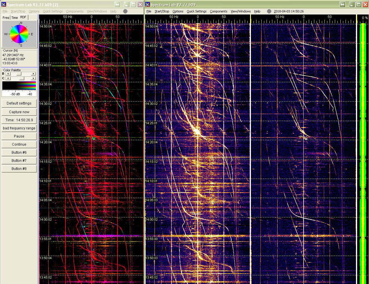
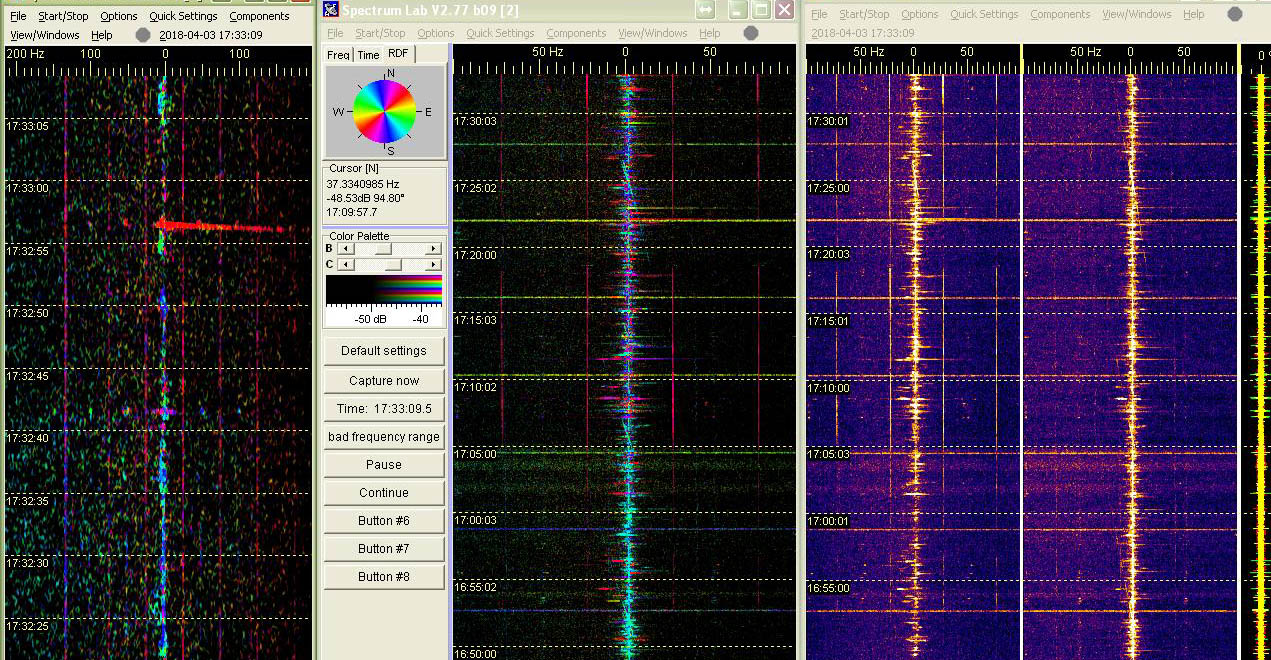
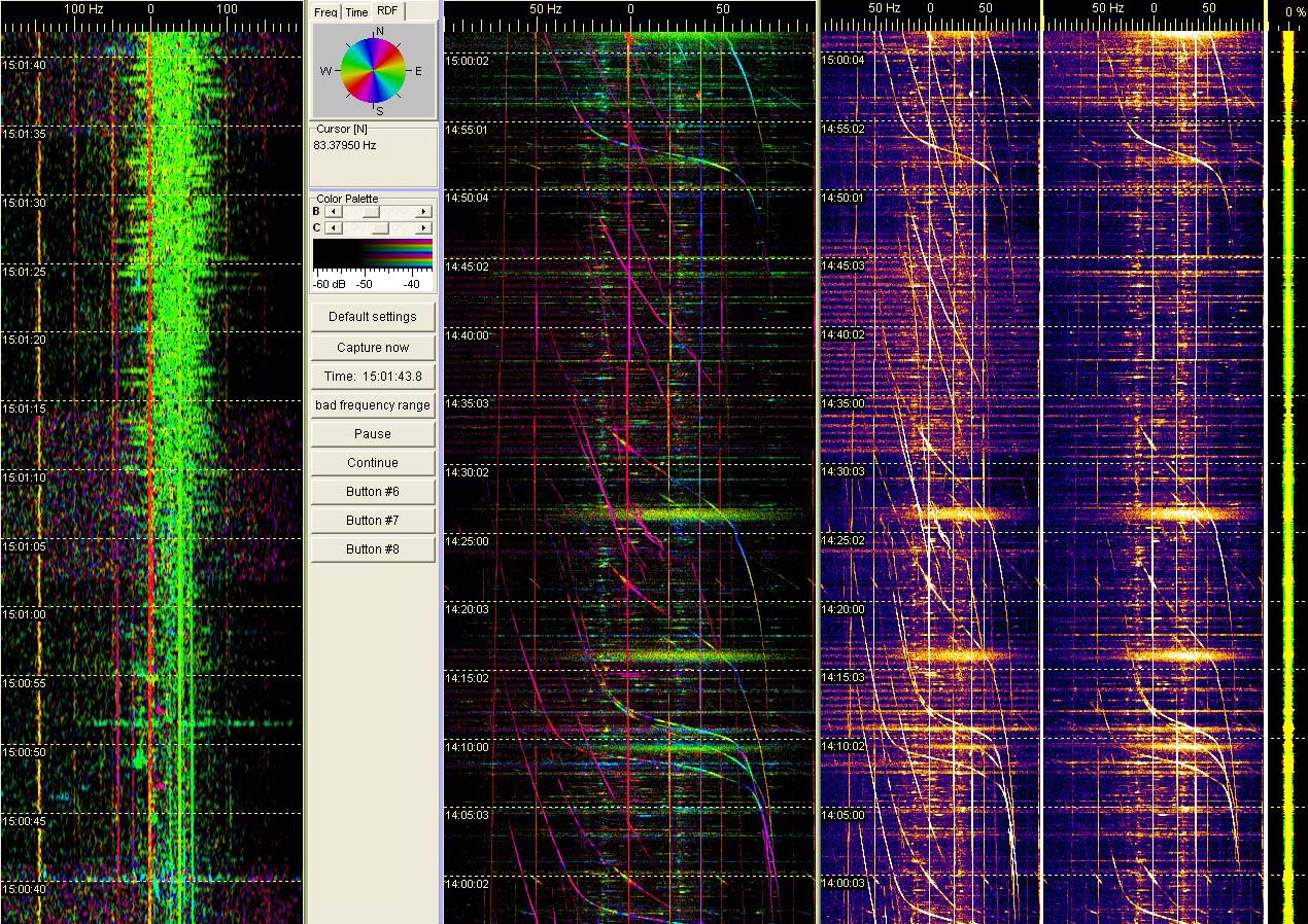
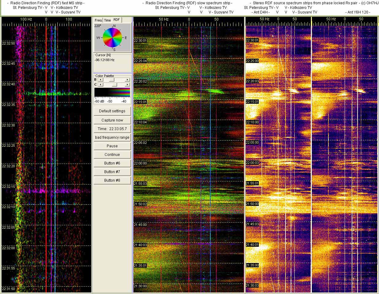
A fast Spectrum Lab Radio Direction Finding (RDF) strip is at left, revealing the precursor burst structure on quick time scale.
At center is a slow RDF strip plotting the noise bursts of aurora precursors tells that they are occurring randomly every few minutes. Narror curves and lines are aircraft scatter (AS) dopplers that change their RDF color by their bearing as they pass by the receiver.
At right is a pair of ‘traditional’ SL strips showing spectrums from the two aerials used for the RDF experiment. Left strip plots St. Petersburg TV carrier frequancy from an omnidirectional 50 MHz 4-el H-dipole array and right strip from a 6-el H-yagi pointing dir 120.
Aerials are 10 m apart from each other. They are not a matched pair with correct separating distance so this RDF direction scale is not calibrated. However, differences of scatter RDF colors indicate differences in scatters directions of arrival related to Rx. Receivers are two FT100’s coupled together to create a phase locked coherent pair suitable for interferometry RDF experiments.
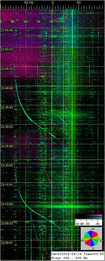
In the midnight, after the evening short ‘aurora precursor’ EDS bursts an actual aurora discharge was ignited with its cloud like wide noise spectrum puffs. The direction of the aurora discharge radio scatters appears to change as the aurora flares move on the aurora front (Aurora oval) surrounding poles. When Northern lights discharge front expands it moves farther from North pole bringing the spectacle visible from north further to aurora spotters in the Central and even Southern parts of Scandinavia.
Usually the aurora discharges start from northeast and gradually move to north and further to northwest until they fade out with the sometimes spectacular ‘flashing’ or ‘dancing’ period of rapidly moving aurora discharge flames before they fade out and retreat beyond northern skyline.
The Spectrum Lab Radio Direction Finding (RDF) function indicates the movements of these Aurora Borealis discharge flares by changing colors. Here is a set of slow narrow spectrum RDF strips of igniting and fading os a rather short period of Northern lights discharge.
These aurora scatters were captured on St. Petersburg TV R1 channel carrier frequency with a homebrew pair of phase locked FT100 ham receivers listening to a yet unmatched RDF pair of 50 MHz aerials. Color indicated directions are not calibrated. Narrow curves are aircraft scatter dopplers and straight lines are TV transmitter carriers and side bands, directions of each indicated by SL RDF colors.
Remark: In these screenshots the short noise puffs of ‘aurora precursors’ appear synchronous with bypassing aircraft dopplers. Maybe jet condensation trail scatter? Or something related to electric discharges agitated by high flying aircraft? Or pure coincidence?
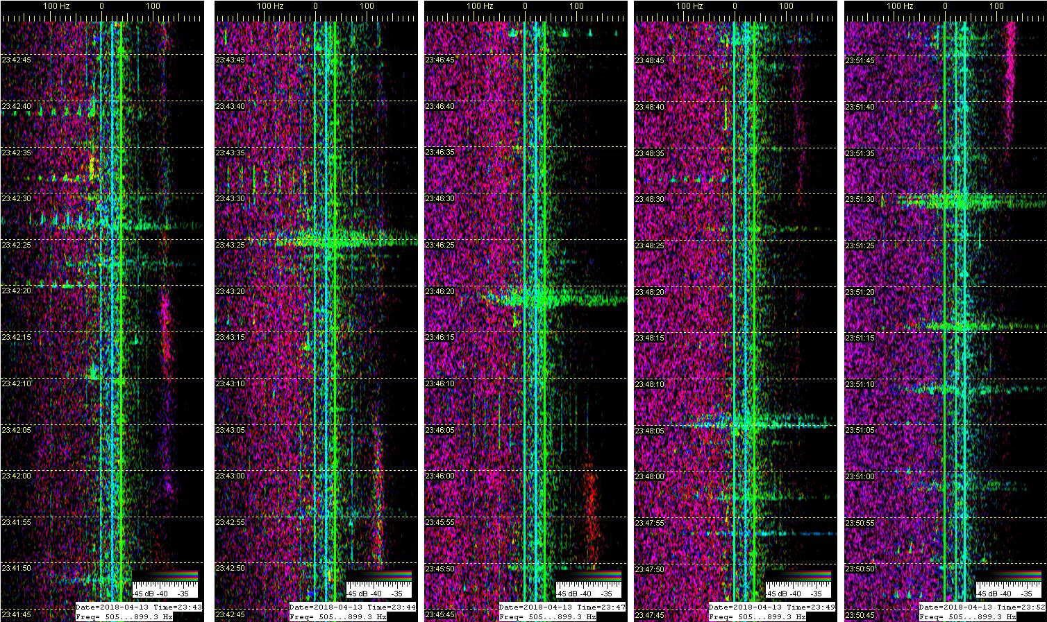
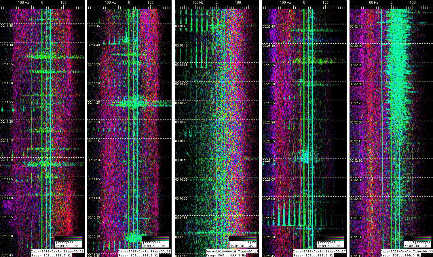
Fast strip radio scatter details of phases of the aurora discharge described in previous report. Captured on St. Petersburg TV R1 carrier frequency.
First set of fast aurora spectrum strips: Igniting fresh aurora discharge is visible as a constant noise spectrum strip left of the three narrow lines of TV carriers. RDF colors indicate directions of each signal. Among are occasional short wide EDS bursts and short sets of TV 50 Hz side bands scattered as narrow MS tails or narrow spectrum EDS.
Second set of strips: The aurora discharce wide noise spectrum appears to live as the aurora scatter noise belt moves or is created on both sides of the TV carrier lines. Third and fourth strips have longer side band scatters. Fifths strip is plotting a long ‘aurora precursor’ burst.
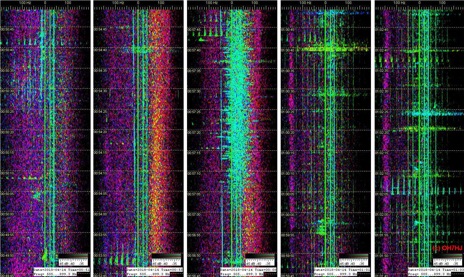
Third set of aurora scatter strips: The aurora discharge gradually fades from its full power shown on the first strip. Second strip shows what seems to be an aurora flare scatter propagating from different direction than from the main aurora discharge front. Third strip has captured an ‘aurora precursor’ burst. Fourth and fifth strips illustrate aurora discharge gradually fading to a narrow noise line at left among natural wide EDS and narrow spectrum 50 Hz TV side band scatters.
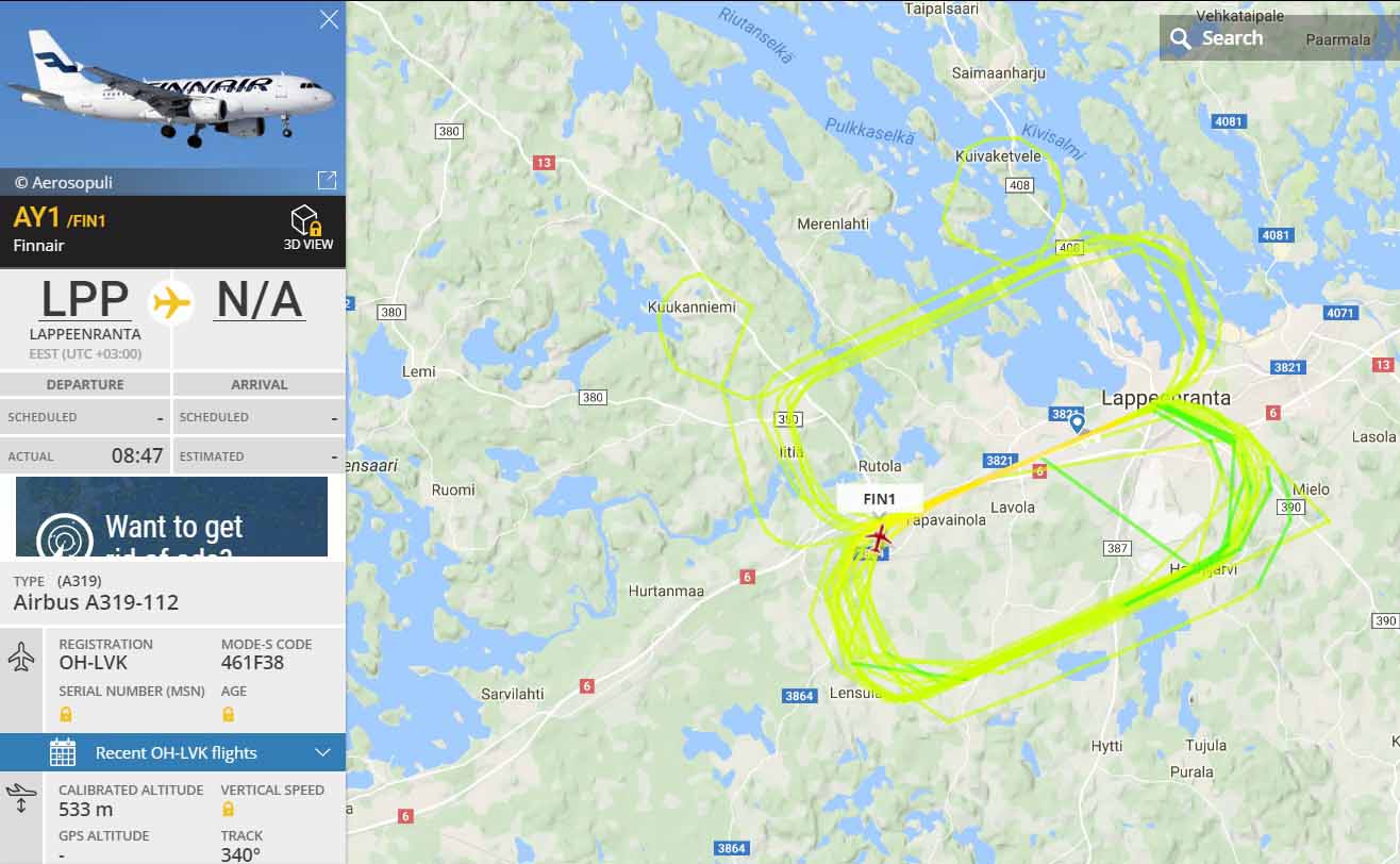
Finnair training flight circling flight route doppler track on St. Petersburg TV carrier frequency. Right Spectrum Lab strip is 200 Hz wide and left strip 100 Hz wide for more details.
A rather low flying aircraft at about half a kilometer altitude and lower at approach is rather well visible on St Petersburg TV carrier. Apparently the low VHF rather long wavelength waves of the powerful TV Tx bend enough down below horizon to illuminate a flight below theoretical radio horizon from the transmitter.
Receiver is a standard cheap RTL dongle listening to a 4-element dipole array aerial and receiving software is a SDR Console V3 streaming 22 kHz wide spectrum of the R1 TV channel to analyzing multi Spectrum Lab windows.
A FR24 playback map illustrates the plane route with training approaches to the EFLP airport.
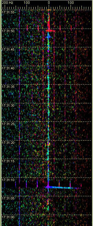
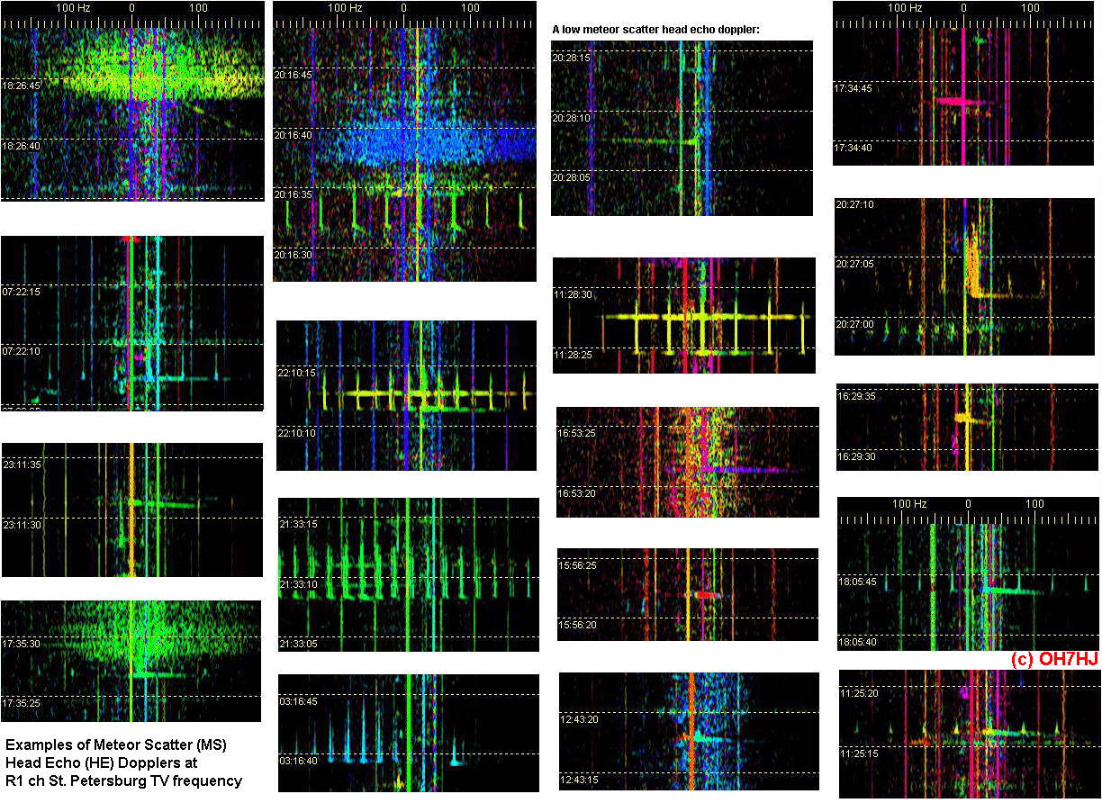
Meteor scatter (MS) head echo (HE) dopplers on radio direction finding (RDF) spectrum strips at St. Petersburg TV frequency. MS head echo doppler scatters are rather weak so it is reasonable to assume that those MS hits occurring between Rx and Tx near the baseline appear stronger on strips by the forward scatter baseline effect than those away from the Rx-Tx baseline.
Although the St. Petersburg TV has a high power R1 ch transmitter these MS HE dopplers appear less frequently on it than on faraway TV Tx’s like on the high power Moscow TV carrier. Reason may simply be that less meteors hit between shorter distance of Rx and Tx than between long distance Rx and Tx. TV Tx aerial radiation vertical pattern may be directed too low for nearby MS hits which may also partially explain why receiver captures less MS HE dopplers on relatively close TV carriers.
These meteor scatters were captured on St. Petersburg TV carrier frequency with a homebrew pair of phase locked FT100 ham receivers listening to a yet unmatched RDF pair of 50 MHz 4 … 6-el aerials. Color indicated directions are not calibrated. Straight lines are TV transmitter carriers and side bands, directions of each indicated by Spectrum Lab software RDF colors.
Capturing MS HE in Europe?
An ideal distance to capture MS HE dopplers on 49749.975 kHz St Petersburg TV might be something like 1000 km away or even more? In countries like Sweden and Norway and Poland the St Petersburg TV should give MS dopplers with fairly good 50 MHz ham aerials. Usual 4 … 6 element 6m band aerials are adequate for capturing MS HE dopplers.
For Poland and Germany, for instance, 49747.398 kHz Moscow TV might be a good source of MS HE. Still more west in Central Europe like in Belgium and NL, some TV Tx’s in East Europe might be good sources of MS HE dopplers.
For Central European MS doppler spotting, candidates of R1 channel TV Tx’s might be for example 49739.360 kHz Kaliningrad. For those having aerials for the R2 TV channel there are more Tx’s, like 59250.007 kHz Kiev.
Nyandoma TV carrier frequency provides more meteor scatter head echo dopplers although its Tx is farther away and has lower power than St. Petersburg TV Tx. An possible explanation for more MS HE hits on remote TV Tx is that more meteors hit between longer distance than between short distance Rx and Tx.
There are also more ‘low MS dopplers’ on Nyandoma TV than on St. Petersburg TV freq. Also this may be caused simply by the longer distance higher number of MS hits. A few of the meteors may hit atmosphere in shallow angle away from the Rx-Tx baseline. In such less usual cases, the path of radio scatter reflection (bistatic range) is extended, creating a ‘low doppler’.
The more regular ‘high MS dopplers’ with their MS head edcho (HE) dopplers mostly on the high doppler shift part of TV carrier are common because meteors usually hit from up to down. Downwards meteor hits create a shortening radio scatter path of reflection which shows on strips as a ‘high doppler’. High dopplers are to the right of the center carrier in the example strips attached.
Usually the ionized ‘meteor trail’ visible as stationary line or set of TV side band lines cools down and fades out from the view of scattering radio waves in a few seconds. Sometimes the trail survives for a number of seconds like the one on the third strip from left of the attached set of MS head echoes on RDF strips.
Tässä leimahtelevien revontulten ‘lieskat’ saavat muodon radiokaikuina. Harrastajavoimin toteutettu revontulitutka kertoo revontulipurkausten suuntien vaihtelut muuttuvina väreinä Spectrum Lab -softan Radio Direction Finding (RDF) -toiminnon avulla.
Tutkaotoksessa oikealla ovat ‘raakanauhat’ kahdelta eri antennilta, joista spektrisofta laskee keskellä näkyvälle nauhalle suunnat väreinä. Vasemmanpuoleisin nauha on tarkoitettu nopeiden ilmiöiden seurantaan.
Revontulipurkausten luonnollisten liikkeiden mukana niiden kohinana kuuluvat ja ‘lumisateena’ spektrinauhoilla näkyvät kaiut liikkuvat dopplersiirtymän johdosta nauhoilla oikealle ja vasemmalle. Seassa näkyvät ohuet kaaret ovat lentokoneiden dopplerkaikuja ja pystysuorat viivat TV-lähetteitä. Aikaleimat nauhojen reunoissa ovat Suomen aikaa.
In English: Flaming Northern Lights on radar spectrum strips. The passive ‘Aurora Radar’ is built by radio hobbyists. It shows directions of high sky Aurora discharge flares as changing colors.
Two separate receiving aerials are used to get the directions of radio waves bouncing back from Northern Lights (Aurora Borealis) discharge front. The ‘snowfall’ like noise clouds on radar strips are radio waves scattering from the aurora discharge flares that are constantly igniting, moving and fading on the ‘Aurora Oval’, a discharge front around Earth poles.
By the article “Limits on radio emission from meteors using the MWA” it looks like formal science is opening its eyes to the spread noise spectrum natural scatters that amateurs have been spotting and explaining for years?
… “broadband radio emission has been observed accompanying bright meteors” …
“The broadband spectra between 20 and 60 MHz were captured” …
… “with a usable bandwidth of 75 kHz tunable to any centre frequency between 10 and 88 MHz. These two events lasted for 75 and 100s, respectively, at 37.9 and 29.9 MHz” …
The pics on paper are not similar spectrum analyzer strips familiar for us with high sky scatter spotting but these quotations suggest that there is something similar on low VHF that they are observing. There is something related to explaining birth of the spread noise spectrum scatters that the article authors appear to miss.
Spread Spectrums by Electric Discharges
Electrostatic experimenters know that scattered radio wave spectrum spread is a characteristic mark of radio waves scattered from air ions accelerated by electrostatic discharge. A high voltage discharge in low pressure gas creates ionization or plasma which modulates scattering radio waves by a noise spectrum.
One may suppose that high atmosphere spread spectrum scatters are created by natural atmosheric electricity discharges. Usual causes of short electric discharge scatters (EDS) appear to be high sky lightning discharges that seem to be triggered either spontaneously or by ionized meteor trails.
Long lasting spread spectrum scatters on 50 MHz appear to be related to such natural electric events as thunderstorm Es and Aurora discharges, for example.
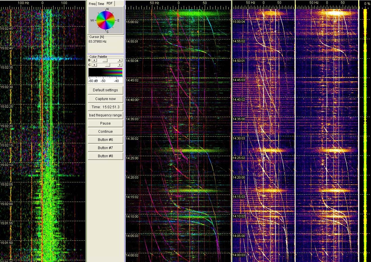
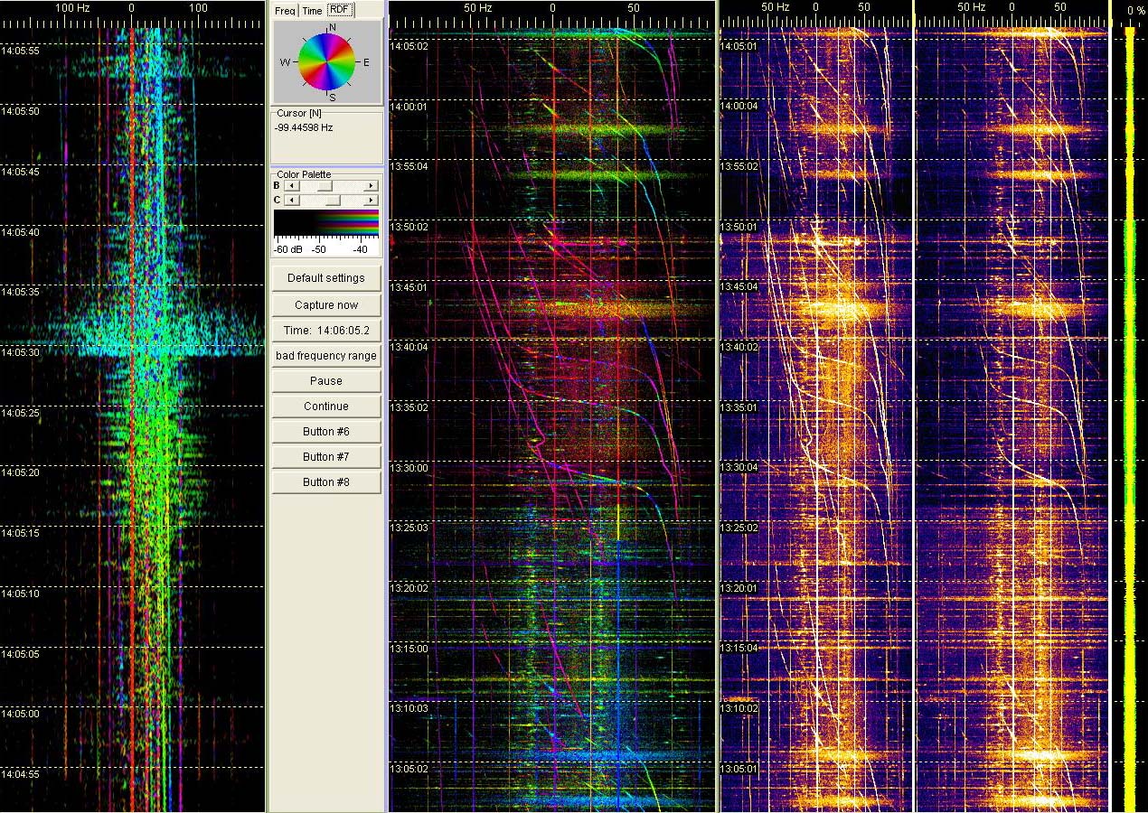
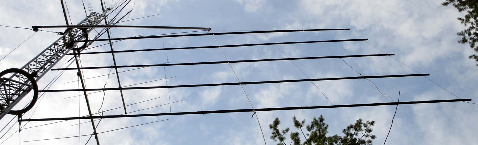
RDF tarkoittaa ‘Radio Direction Finding’. Tämä ‘kvadimattoantenni’ (quad array) koostuu kahdesta identtisestä 4-el kvadista puolen aallonmitan päässä toisistaan. Kumpaakin syötetään erikseen samanmittaisilla koakseilla samanlaisille hamssivastaanottimille, jotka on vaihelukittu koherentiksi pariksi. Vastaanottimien äänet syötetään stereoäänikortin kautta tietsikalle, jolla Spectrum Lab -softan RDF-toiminto laskee spektrissä näkyvien radioaaltojen tulosuunnat vertaamalla niiden vaihe-eroa. Kyseessä on siis radiosuuntiminen interferometriamittauksella.
SL erottelee värein kaikki spektrissä näkyvät signaalit niiden tulosuuntien mukaan. Pääsuunnan lisäksi kahden antennin interferometria antaa peilisuunnan. Usean antennin interferometrialla menetelmä tarkkenee, ja kykenee mittaamaan myös saapuvan aallon vertikaalikulman. Radiosuuntimat näkyvät RDF-spektrinauhoilla väreinä tutkanauhakuvan vasemmassa ylänurkassa olevan väriympyrän mukaisesti. Spektrikuvina vasemmalla näkyy nopea RDF-nauha, keskellä hidas RDF, ja oikealla kummankin antennin spektrit erikseen ‘raakoina’ ilman radiointerferometriaa.
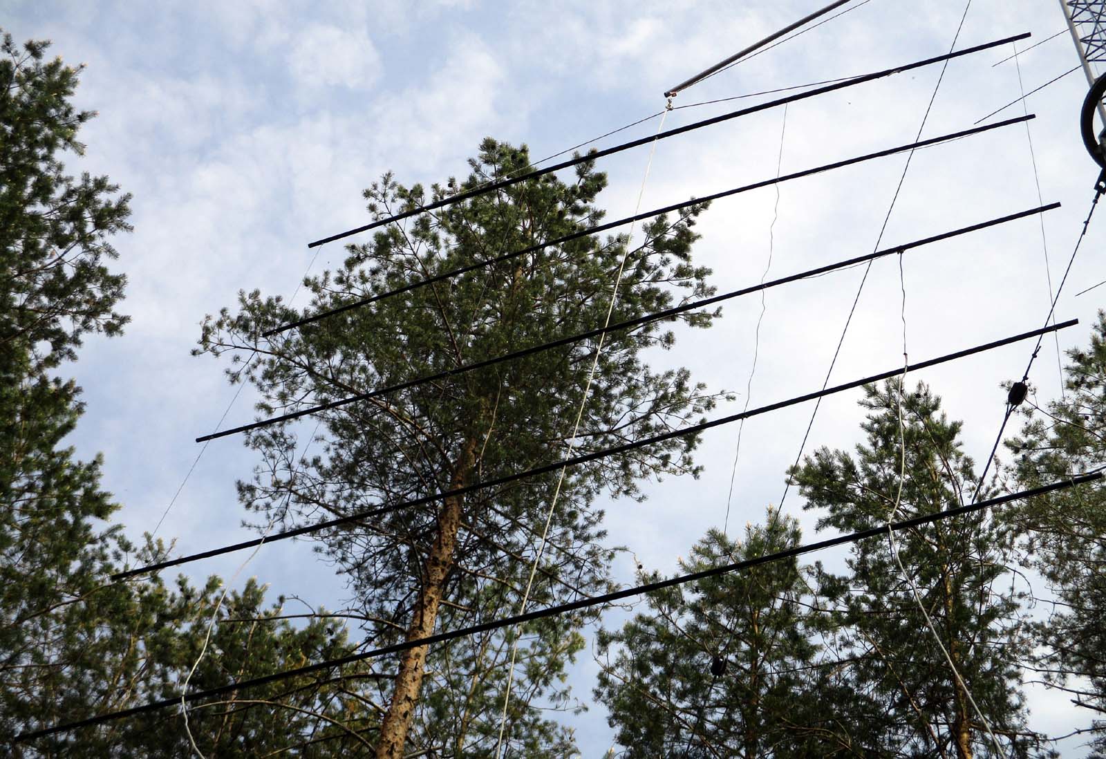
Antennin suuntakuvio muistuttaa yhtä vaakakvadia tai -dipolia kaksoiskeiloineen. Kvadiparin sivut on suunnattu Pietarin TV:n suuntaan vaimentamaan vahvaa TV-kantoaaltoa ‘häikäisemästä’ heikkoja dopplereita ja muita taivaskaikuja. Kvadipari on kiinteästi suunnattu, eikä siis pyöri maston mukana. Runkomateriaalina antenniparissa on lasikuituputki. Elementtilankana on eristetty puhelinparikaapeli halkaistuna. Antenniparin korkeus on 6 m, leveys 4,5 m ja paino 5,7 kg.
In English:
A 50 MHz band double 4-element horizontal quad array 2Q4H for interferometry radio direction finding i[/i] lifted up and hanging from a crane built for it to mast. Aerial is made of glass fiber tubes supporting insulated driven ‘skeleton quad’ flexible insulated wire elements. [/b]
High impedance quad arrays are matched to their 75 ohm TV coaxes with 120 cm sections of 105 ohm twin lead. Quad pair dimensions: Height 6 m, width 4.5 m and weight 5,7 kg. Both RDF 4-el quad sets of the identical pair are connected with feed coaxes of same length to similar ham receivers which are phase locked to create a coherent pair. The audios from the receivers are fed to computer stereo sound card inputs and analyzed with Spectrum Lab (SL) software RDF option.
Resulting SL RDF spectrum strips show signals propagating from different directions with different colors. The direction scales of these screenshots are not yet calibrated. At left is a fast SL RDF strip for spotting short lifetime high sky scatters like meteor scatter head echoes (MS HE) dopplers and spread spectrum electric discharge scatters (EDS) of high altitude ionospheric lightnings. Middle strip is slow for RDF observations of long lasting events like aircraft dopplers, Es and aurora scatter. At right are ‘raw’ input spectrums from both receivers.
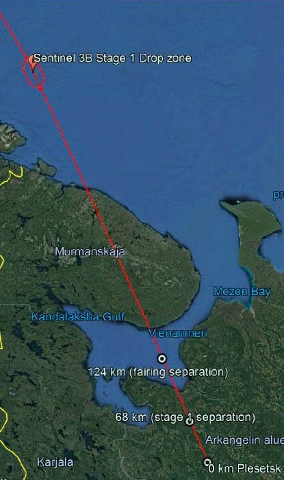
A pair of spacecraft launch dopplers appeared in sound tracks recorded with a standard ham 6m band 6-element yagi antenna and a cheap RTL receiver (Rx). The transmitter (Tx) that had provided the faint but clear fast object dopplers was Moscow TV.
This is surprising because it is one of the most distant of regularly spotted TV Tx’s measured from the spacecraft launch site. However, thinking further, it makes sense.
Moscow Ostankino TV has a high power Tx with about 200 kW ERP power and its transmitting aerial lobes reach high enough from ground far away near the trajectory of the rapidly rising spacecraft, thanks to the long distance and Earth curvature.
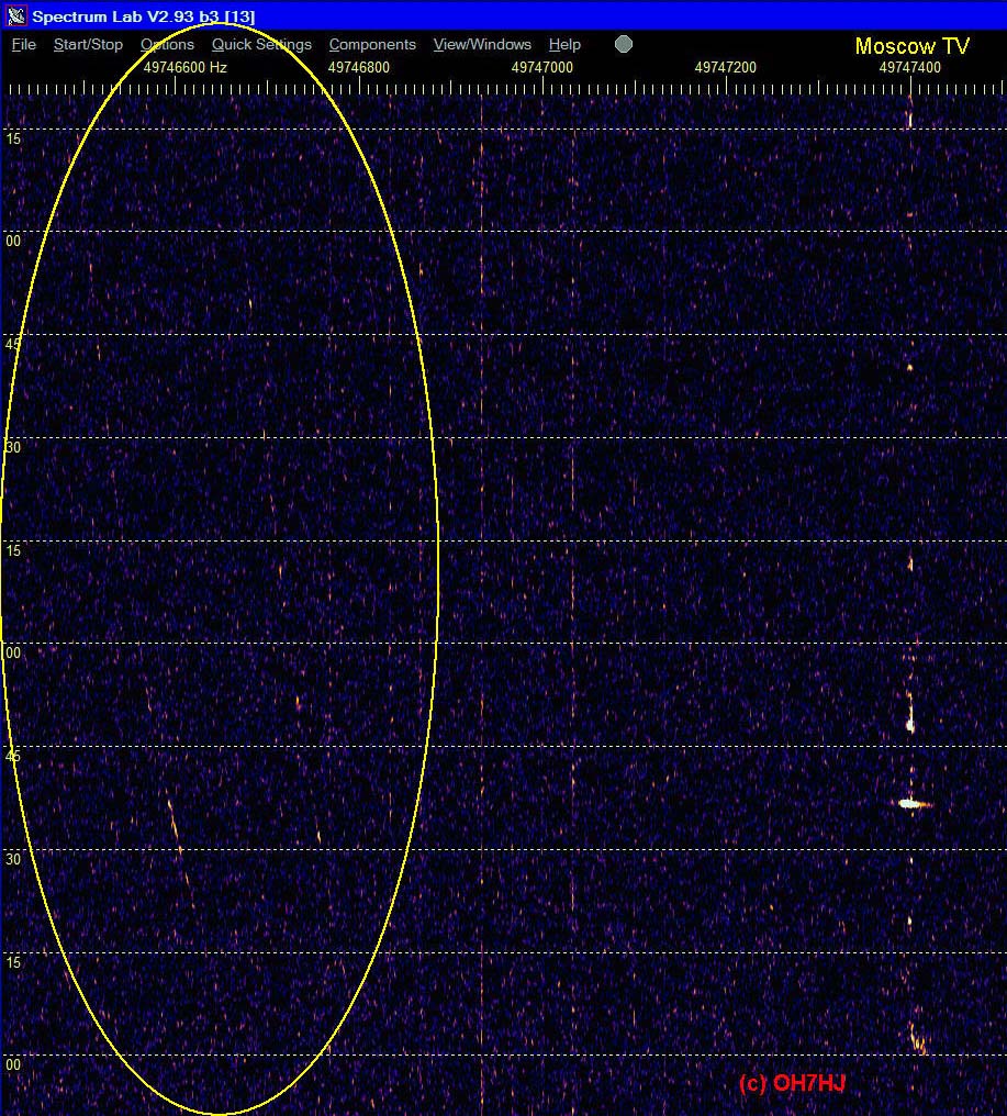
Dopplers on Strips:
There are two faintly visible dopplers marked 1. and 2. Please click attached pics to extend them. They show a large enough doppler shift to be created by a departing orbital carrier rocket. Direction of doppler shift is low quite as it should be for a HFO moving away related to Moscow TV Tx. The fading of the dopplers appear distinctive to faraway scatters.
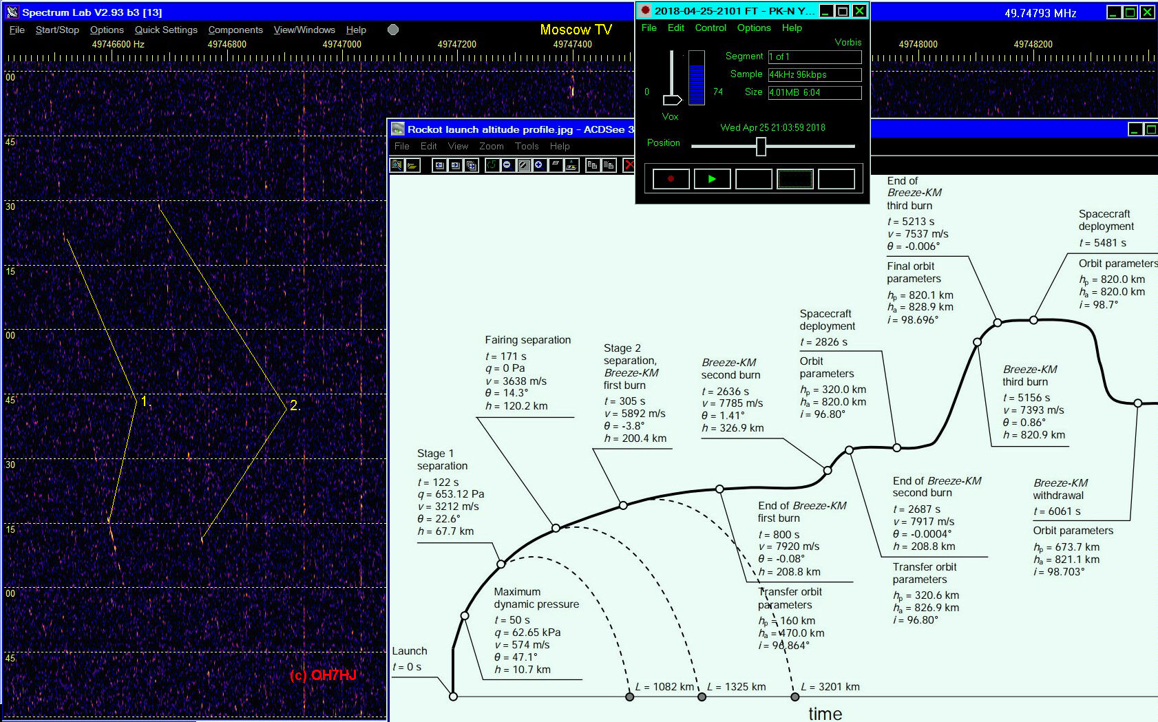
The doppler 1. at left appears to be by its doppler shift from a faster high flying object (HFO) and the doppler 2. at right from a slower HFO. The faster one appears to be created by the accelerating rocket stage and the slower one a jettisoned earlier carrier stage of the rocket.
Attached are copies edited with markings from the recording replay of the 6-el NNE pointing yagi Moscow TV spectrum strips. Time ticks on strips are 15 s apart. Visible time stamps are not calibrated to original observations time because strip is made from a recording.
The Rec-All Pro replay window is showing original observation time as Finnish local (UTC + 3h). Frequency scale is above with Moscow TV carrier position marked. Receiving software was SDR Console V3 and analyzing software was Spectrum Lab.